Welcome to our new website, found an issue or bug? Please report it here
Series-AFG
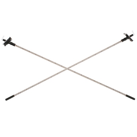
Duct-Mounted Pressure Sensor for Air/Gas Flow; Easy Install, 60" Ducts
- Kit complete with 2 probes and installation hardware
- Trimmable length for any duct size up to 60"
- Alternative to costly air flow stations
Series-AFG
From
$
799.00
Product Overview
- Accuracy ± 5 %
- Diameter 0 in
- Duct Diagonal, Max 60.4 in
- Duct Diameter, Max 59.4 in
- Height 0 in
- Materials, Wetted Acetyl, Neoprene, Polyurethane, PVC, Stainless Steel
- Media Compatibility Air, Argon, Compatible Gases, Nitrogen
- Operating Temperature, Max 176 °F
- Process Connection Size 5/16 in
- Process Connection Type Barbed Fitting
- Velocity, Max 5904 FPM
- Velocity, Min 295.2 FPM
The Series AFG Flow Grid is an outstanding simple yet accurate cost effective alternative to other duct mounted pressure sensors. Once installed and connected to a suitable measuring instrument, the device will provide years of trouble free monitoring of both air and gas flow. Installing the AFG Flow Grid is quick and easy, the AFG is supplied in kit form to allow both workshop and on-site installation into a wide range of square and circular ducts up to approximately 60". The AFG Flow Grid is a fundamental pressure sensing device designed to transmit a continuous differential pressure signal. When this output is connected to a suitable measuring instrument (i.e., manometer, pressure transducer, etc.), it may be used to determine air velocity and volume flow rate.
How the AFG Flow Grid Works
The AFG Flow Grid consists of two tubes mounted diagonally across a square or rectangular duct, or diametrically across a round duct. The tubes are drilled with a series of equi-spaced holes. The holes in one tube face directly upstream and sense total pressure, while the pairs of holes in the second tube also face forward but at an included angle of 79 degrees, sensing static pressure. The total and (sub) static pressures are averaged along the length of each tube and provide pressure signals at connectors outside the duct wall. The pressure differentials across these connectors constitute the output signal.
Product Applications
- To display differential pressure, velocity or volume flow using a micro manometer, gage, or transmitter
- To give a warning of over or under flow rate using a pressure switch
- To control air supply in a system by connecting the grid to a pressure transmitter with an electrical output which can be used to feed into a control system
- To display differential pressure on a simple fluid manometer to give visual indication of changes in volume flow rate in the duct