Thermocouples are widely utilized temperature sensors for industrial and scientific applications – the appeal lying in their simplicity, ruggedness, and ability to measure a wide range of temperatures. However, to ensure accurate readings, thermocouple circuits must account for cold junction compensation.

What is Cold Junction Compensation?
In any thermocouple-based temperature measurement system, the output voltage corresponds to the temperature differential between two junctions: the measuring (hot) junction and the reference (cold) junction. This voltage is governed by the Seebeck effect, and, by itself, it provides no indication of absolute temperature – only the difference between the two junctions.
This introduces a critical problem: If the temperature at the cold junction is unknown or not properly accounted for, the calculated temperature at the hot junction will be incorrect.
Thermocouple tables are standardized based on a reference junction temperature of 0 °C. Unless the cold junction is physically maintained at 0 °C (as was historically done with ice baths), the raw thermocouple voltage must be corrected – or compensated for – based on the actual cold junction temperature to ensure accurate readings.
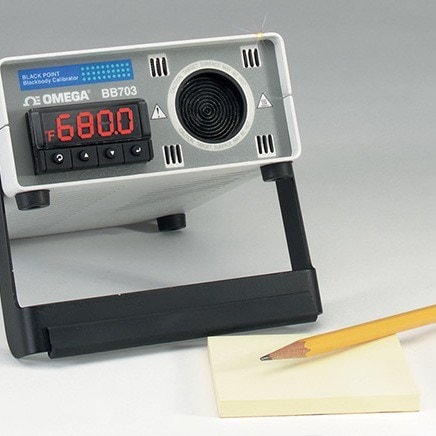
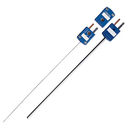
Explore DwyerOmega's Entire Temperature Product Selection
Real-World Implications
Consider an example where the thermocouple is measuring a process at 400 °C, and the cold junction is at 30 °C. The thermocouple generates a voltage that represents a 370 °C differential. If the measurement system incorrectly assumes the cold junction is at 0 °C, it will underreport the process temperature by 30 °C, introducing a significant error.
In industrial and critical process environments, this level of inaccuracy can lead to:
- Product quality issues
- Regulatory compliance failures
- Equipment malfunction or unsafe operating conditoins
How Cold Junction Compensation Works
Cold junction compensation is the process of correcting for the temperature at the reference junction to accurately determine the temperature at the measuring junction - any variation in the reference junction's temperature must be corrected for in order to avoid inaccurate readings. This process is critical to ensuring the accuracy of thermocouple-based temperature measurements in real-world environments.
Modern Industrial Instrumentation (Digital Cold Junction Compensation)
Modern instrumentation solves this issue by integrating a temperature sensor—usually a resistance temperature detector (RTD) or sometimes a thermistor — at the terminal block where the thermocouple wires connect to the measurement system. Because this junction is exposed to ambient conditions, its temperature is rarely fixed and can fluctuate throughout the day or due to nearby equipment. These fluctuations directly affect the thermocouple’s voltage output, since thermocouples measure temperature differentially, based on the voltage generated between the measuring (hot) junction and the reference (cold) junction.
To compensate for this, the RTD near the terminal block continuously measures the actual temperature of the cold junction. This temperature is then fed into the instrument’s signal processing algorithm, which uses standard thermoelectric reference tables (like NIST tables) specific to the thermocouple type (e.g., Type K, J, T, etc.). The instrument first determines what the thermoelectric voltage would be if the cold junction were at 0 °C. It then mathematically combines this with the measured voltage from the thermocouple to calculate the true temperature at the hot junction.
In effect, the system adds the voltage that would be generated between 0 °C and the measured cold junction temperature to the voltage produced between the cold and hot junctions. This two-step process — measuring the cold junction temperature and applying a correction based on known thermocouple behavior — yields a final, accurate temperature reading for the measuring junction. Because this is done automatically and continuously in real time, modern cold junction compensation enables reliable temperature monitoring even in dynamic or harsh environments, without requiring manual recalibration or external reference conditions.
| Feature | Digital Method | Electrical Bridge Method |
|---|---|---|
| Compensation Mechanism | Digital sensor (RTD, thermistor, or IC) with microcontroller | Analog bridge with temperature-sensitive resistor |
| Cold Junction Sensing | Embedded temp sensor at terminal block | Thermally coupled resistor in bridge leg |
| Correction Type | Software-based voltage adjustment using lookup tables | Analog voltage correction via bridge imbalance |
| Reference Temperature Handling | Dynamically references 0°C using NIST tables | Simulates fixed 0°C reference via circuit design |
| Accuracy | High; typically ±0.5°C or better | Moderate; depends on calibration and stability |
| Environmental Sensitivity | Robust; better thermal isolation and filtering | Prone to drift and noise if not well shielded |
| Power Requirements | Standard low-voltage DC, often integrated | Requires stable analog DC supply (e.g., mercury battery) |
| Common Usage Today | Universal in modern instruments and DAQs | Legacy systems, educational use |
Electrical Bridge Method
Before the widespread use of digital electronics and microprocessor-based instrumentation, cold junction compensation in thermocouple systems was commonly implemented using analog circuitry - specifically, the electrical bridge method. While largely obsolete today, this method laid the foundation for modern compensation techniques and is still relevant for understanding thermocouple theory and legacy system design.
This technique employed a self-compensating bridge circuit incorporating a temperature-sensitive resistor (typically an RTD or thermistor) thermally bonded to the cold junction (reference junction). The resistor formed one leg of the bridge network, which was energized by a stable DC voltage source.
As the ambient temperature at the cold junction varied, the resistance of the sensor changed accordingly, introducing an imbalance in the bridge. This imbalance would create a voltage that was used to simulate a reference junction at a fixed temperature, usually 0 °C, aligning with standard thermocouple calibration tables.
Contact a DwyerOmega Expert Today!

What is a Calibrator and why is it an important device? Introduction to Instrument Calibration