1-800-663-4209 | Your feedback matters, take a quick survey Website Feedback
HBM-M-Rosette
Rosette Strain Gauges for High Temps & Alternating Load Resistance
- High Resistance to Alternating Loads
- High Temperature Range 300°C (572°F)
- Wide Spectrum of Different Types
- All models sold in a 5-pack, except 1-LM11 which are sold in a 10-pack
HBM-M-Rosette
From
$
378.69
Product Overview
- Bend Radius, Min 5 mm
- Carrier Thickness 35 μm
- Electrical Connection Solder Pads
- Elongation 10000 µm to 15000 µm
- Encapsulation Thickness 25 μm
- Gauge Factor 2.2
- Grid Style 3 Grid Rosettes
- Grid Thickness 5 μm
- Lead Length 0 m
- Material Expansion Compensation N/A
- Materials Chromium-Nickel, Polyimide, Glass Fiber Reinforced Phenolic
- Mechanical Life 10⁷ cycles
- Mechanical Life Note 10⁷ cycles at 2000 um/m,10⁶ cycles at 2200 um/m, 10⁴ cycles at 3100 um/m
- Nominal Resistance 350 Ω
- Operating Temperature, Max 300 °C
- Operating Temperature, Min -200 °C
- Pack Size 5
- Resistance Tolerance ±0.3%
- Strain, Max 10,000 µm
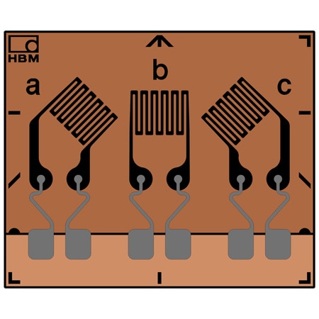
Rosette Strain Gages have three measuring grids arranged at an angle of 0°/45°/90° or 0°/60°/120°.
M Series strain gauges have been specially developed for high resistance to alternating loads at increased strain levels and high temperatures up to 300°C (572°F). They are foil strain gauges with measuring grids made of a special nickel-chromium alloy. OMEGA/HBM offer this special strain gauge with various geometries, measuring grid lengths and temperature response matching.
New materials offering high strength such as fiber composites pose a major challenge for strain gauges used for measurements specifically when pushing components to their mechanical limit of performance. Situations may arise where a strain gauge subjected to alternating loads at increased load levels is weakened and fails earlier than the component under test. The M Series has been specially developed for high resistance to alternating loads and allows for testing of materials featuring high strength.
All M Series strain gauge types are available with different measuring grid lengths:
• 1.5 mm: where space is a constraint or when highly selective measurement results are required
• 3 mm: for inhomogeneous materials and where space is a requirement or not
• 6 mm: for inhomogeneous materials and where space is not a requirement
The right measuring grid length: The measuring grid length depends on the aim of measurement, since the result of a measurement with strain gauges will be determined as the average of strains. In general, measuring grid lengths of 3 to 6 mm (0.06 to 0.24') generates a better result.
Long measuring grids are recommended where there is an inhomogeneous material such as concrete or wood. A long strain gauge will bridge the inhomogeneity of the work piece and return the strain underneath the measuring grid as the measurement result.
Short measuring grids are suitable for detecting a local strain state. Therefore, they are suitable for determining strain gradients, the maximum point of notch stresses and similar stresses.
Specifications
Strain Gage Construction–Foil Strain Gauge
Carrier:
Material: Glass fiber reinforced phenolic
Thickness: 35 ±10 µm
Grid Foil:
Material: CrNi
Thickness: 5 µm
Encapsulation:
Material: Polyimide film
Thickness: 25 ±5 µm
Connections: Solder pads with strain relief
Resistance: 350 and 1000 Ω
Resistance Tolerance: ±0.3%(1)
Gage Factor: Approximate 2.2 (specified on each package)
Gage Factor Tolerance: ±1.5% (for grid length <3 mm) ±0.7% (for grid length ≥3 mm)
Temperature Coefficient of the Gauge Factor: Specified on each package
Transverse Sensitivity: Specified on each package
Operating Temperature Range: -200 to 300°C (-328 to 662°F)
Temperature Response (Ferrite Steel): 10.8 ppm/K (6.0 ppm/°F)
Maximum Elongation:
Positive Direction: 10,000 µm (1%)
Negative Direction: 15,000 µm (-1.5%)
Minimum Bending Radius: 5 mm (0.20') for linear gauges 10 mm (0.39') for stacked rosettes
Bonding Material that Can Be Used: Z70 or EP310S
Fatigue Life (Test to Failure):
107 cycles at 2000 µm/m
106 cycles at 2200 µm/m
104 cycles at 3100 µm/m
PDFs & Manuals
Show Ratings & Reviews
What is the Sensitivity of this in mV/V scale
Raje, you have a three grid strain gauge, so to measure the X Y and Z component of strain you will typically complete them as three individual quarter bridges. Once you have three quarter bridges, you will have to calculate the mV output based on the Resistance and GF of the strain gauge. Please refer to: https://www.omega.co.uk/techref/pdf/StrainGageCalcs.pdf If you have more question, please reach us at 1800 622 2378
Date published: 2024-03-19