Welcome to our new website, found an issue or bug? Please report it here
FLMG-Series
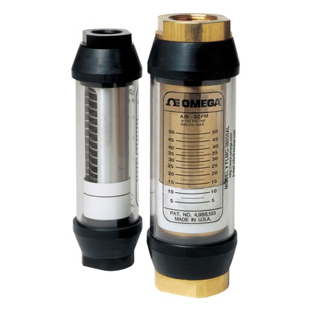
Variable Area In-line Flow Meters For Air
Models In Stock
- Monitoring Most Pneumatic or Compressed Gas Systems
- Flow Rates From 1 to 900 SCFM @ 100 psi
- High Pressure: to 600 psi for Brass or Aluminum, 1000 psi for Stainless Steel
- High Temperature—to 116°C (240°F) Standard, 204 or 316°C (400 or 600°F) Optional
FLMG-Series
From
$
350.85
Models In Stock
Product Overview
- Accuracy ± 4 %
- Mechanical Life >10^6 cycles
- Media Compatibility Air
- Number of Tubes 1
- Process Connection Type NPT Female
- Process Temperature, Max 116 °C
- Repeatability ± 1%
- Scale Direct Read
- Scale Media Calibration Air @ 100 psi
- Standard Calibration Fluid Air @ 21°C (70°F), 1.0 sg and 6.8 bar (100 psig)
- Valve Included false
The FLMG flow meters feature rugged construction, easy installation, and direct-reading flow rates of air. The units are calibrated at 100 psi pressure, suitable for most compressed pneumatic applications.
The spring-and-piston type assembly enables these flow meters to be mounted in any position. The FLMG models with optional analog output (-MA) are typically used to transmit a signal proportional to the flow rate to a process controller, a PLC, a recorder, or a panel-mount display. With the -MA option, the user can choose between reading a 0 to 2000 Hz square-wave pulse, a 0 to 5 Vdc analog signal, or a 2-wire 4 to 20 mA analog signal by connecting the appropriate pins.
SPECIFICATIONS
Measuring Accuracy: ± 4% FS over the entire scale range
Repeatability: ± 1% FS
Flow Measuring Range: 1.2 to 900 SCFM
Maximum Operating Pressure:
Aluminum and Brass Monitors: 40 bar (600 psig)
Stainless Steel Monitors: 70 bar (1000 psig) up to 116°C (240°F)
Maximum Operating Temperature: 116°C (240°F)
Note: For options “-HT” and “-UHT”, see high-temperature graph on spec sheet
Pressure Differential: See the pressure graphs on spec sheet.
Standard Calibration Fluids: Air @ 21°C (70°F), 1.0 sg and 6.8 bar (100 psig)
Relay (Optional): 1 or 2 form “C” relays, rated 10 A, 125 or 250 Vac or ¼ A, 250 Vdc
Mechanical Life: >106 cycles
Analog Output (Optional): Supply voltage 12 to 35 Vdc, field selectable for 0 to 5 Vdc (100 W minimum load), 0 to 2000 Hz square-wave pulse or 4 to 20 mA
Rmax = 50 (Vs - 12)
(Vs = supply voltage DC)
Installation Dimensions:
1/4 and 1/2 NPT Sizes: 1-7/8 OD x 6-9/16" length
3/4 and 1 NPT Sizes: 2-3/8 OD x 7-5/32" length
1-1/4 and 1-1/2 NPT Sizes: 3-1/2 OD x 10-1/8" length
| Description | Aluminum | Brass | Stainless Steel |
| High pressure casing, end ports and tapered shaft | Aluminum | Brass | 304 SS |
| Seals | Buna (std), EPR, FKM or perfluoroelastomer | Buna (std), EPR, FKM or perfluoroelastomer | FKM with PTFE backup (std) Buna, EPR or perfluoroelastomer |
| Transfer Magnet | PTFE-coated Alnico | PTFE-coated Alnico | PTFE-coated Alnico |
| Floating Orifice Disk | Stainless Steel | Stainless Steel | Stainless Steel |
| All Other Internal Parts | Stainless Steel | Stainless Steel | Stainless Steel |
| Description | Aluminum | Brass | Stainless Steel |
| Window Tube | Polycarbonate (std), Pyrex® | Polycarbonate (std), Pyrex® | Polycarbonate (std), Pyrex® |
| Window Seals | Buna (std) | Buna (std) | Buna (std) |
Show Ratings & Reviews
Rated 4 out of
5
by
Masood from
Good product
I just bought this and I am happy so far with its performance.
Date published: 2017-10-08