Welcome to our new website, found an issue or bug? Please report it here
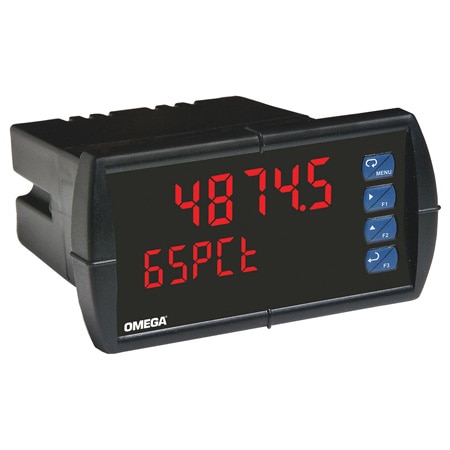
DP6000-6R4
1/8 DIN Process Panel Meter
Choose a Variant
Output Configurations
Input Type
Supply Voltage
Control Output
Volume discounts available
Volume Discount Schedule
| Quantity | Price each |
|---|---|
| 1-9 | C$916.62 |
| 10-24 | C$870.79 |
| 25-49 | C$824.96 |
| 50-99 | C$779.13 |
| 100-499 | C$733.30 |
| 500+ | C$687.47 |
Added to Your Shopping Cart
Configuration complete.
Please add to cart to keep it or exit the configuration
Please add to cart to keep it or exit the configuration
Failed to Save Configurations, Click on Configure Button Start Again
Product Specs
<< See all Product Models| Brand |
|
| Additional Features 1 | Standard |
| Baud Rate | 300 to 19200 |
| Calibration | Calibrated at the factory. Recalibration is recommended at least every 12 months |
| Category of Overvoltage | II |
| Category of Overvoltage Note | Installation overvoltage category II; local level with smaller transient overvoltages than installation overvoltage category III |
| Control Output | 4 SPST Relay |
| Data Interface | Modbus RTU |
| Data Interface Note | Protocol: Modbus RTU Meter Address/Slave ID: 1 – 247 Baud Rate: 300 to 19,200 bps Transmit Time Delay: Programmable between 0 and 199 ms Data: 8 bit (1 start bit, 1 or 2 stop bits) Parity: Even, odd, or none with 1 or 2 stop bits Byte-to-Byte Timeout: 0.01 to 2.54 seconds Turn Around Delay: Less than 2 ms (fixed) |
| Digital I/O Note | Channels: 4 digital inputs and 4 digital outputs per module System: Up to 2 modules for a total of 8 inputs and 8 outputs Digital Input Logic: High: 3 to 5 Vdc Low: 0 to 1.25 Vdc Digital Output Logic: High: 3.1 to 3.3 Vdc Low: 0 to 0.4 Vdc Source Current: 10 mA maximum Sink Current: 1.5 mA minimum +5 V Terminal: To be used as pull-up for digital inputs only |
| Display Color | Red |
| Display Size | 15 mm (0.60 in) |
| Display Type | 6 Digit Dual - Line |
| Display Type Note | Both displays are 6 digits (-99999 to 999999), red LEDs with leading zero blanking Upper Display: 15 mm (0.60") high Lower Display: 12 mm (0.46") high Display Intensity: 8 intensity levels Display Update Rate: 5 per second Overrange: Display flashes 999999 Underrange: Display flashes -99999 Display Assignment: The upper and lower displays may be assigned to PV1, PV2, PCT (percent), max/min, alternate max and min, set points, units (lower display only), or Modbus input |
| Electrical Connection | Screw Terminal |
| Electrical Connection Note | Removable screw terminal blocks accept 12 to 22 AWG wire, RJ45 for external relays, digital I/o, and serial communication adaptors |
| Enclosure Material | Plastic |
| Enclosure Ratings | IP65, NEMA Type 4X |
| Form factor | 1/8 DIN |
| Functions | Noise Filter: Programmable from 2 to 199 (0 will disable filter) ;Filter Bypass: Programmable from 0.1 to 99.9% of calibrated span ;Cyber Security: 3 programmable passwords restrict modification of programmed settings; Pass 1: Allows use of function keys and digital inputs; Pass 2: Allows use of function keys, digital inputs and editing set/ reset points; Pass 3: Restricts all programming, function keys, and digital inputs |
| Fuse Rating | 5 A delayed |
| Height | 62 mm |
| Input Type | Current, Voltage |
| Input Type Note | Input: Field selectable: 0 to 20 mA, 4 to 20 mA, ±10 Vdc (0 to 5, 1 to 5, 0 to 10V), MoDbuS PV (slave) Accuracy: ±0.03% of calibrated span ±1 count, square root and programmable exponent accuracy range: 10 to 100% of calibrated span Temperature Drift: 0.005% of calibrated span/°C max from 0 to 65°C ambient, 0.01% of calibrated span/°C max from -40 to 0°C ambient Signal Input Conditioning Function: Linear, square root, programmable exponent, or round horizontal tank volume calculation Multi-Point Linearization: 2 to 32 points for PV or PV1; 2 to 8 points for PV2 (dual-scale level feature) Programmable Exponent: 1.0001 to 2.9999 Low-Flow Cutoff: 0 to 999999 (0 disables cutoff function) Decimal Point: Up to 5 decimal places or none: d.ddddd, dd.dddd, ddd.ddd, dddd.dd, ddddd.d, or dddddd Calibration Range: 4 to 20 mA: Minimum span; input 1 and Input 2: 0.15 mA ±10 V: Minimum span; input 1 and 2: 0.10 V An Error message will appear if input 1 and input 2 signals are too close together Input Impedance: Voltage Ranges: Greater than 1 MΩ Current Ranges: 50 to 100 Ω (depending on resettable fuse impedance) Input Overload: Current input protected by resettable fuse, 30 Vdc max; fuse resets automatically after fault is removed |
| Isolation | 4 kV input/output-to-power line; 500 V input-to-output or output-to-P+ supply |
| Length | 143 mm |
| Memory | Non-Volatile Memory : All programmed settings are stored in non-volatile memory for a minimum of ten years if power is lost |
| Mounting | 1/8 DIN panel cutout required: 92 x 45 mm (3.622 x 1.772"); two panel mounting bracket assemblies are provided |
| Normal Mode Rejection | Greater than 60 db at 50/60 Hz |
| Number of Inputs | 1 |
| Operating Temperature, Max | 65 °C |
| Operating Temperature, Min | -40 °C |
| Output Configurations | None |
| Output Detail | Rating: 2 or 4 SPDT (Form C) internal and/or 4 SPST (Form A) external; rated 3 A @ 30 Vdc and 125/250 Vac resistive load; 1/14 HP (≈ 50 W) @ 125/250 Vac for inductive loads such as contactors, solenoids, etc. Noise Suppression: Recommended for each relay contact switching inductive loads Deadband: 0 to 100% of span, user programmable High or Low Alarm: User may program any alarm for high or low trip point; unused alarm LEDs and relays may be disabled (turned off) Relay Operation: Automatic (non latching), latching (requires manual acknowledge), sampling (based on time), pump alternation control (2 to 8 relays), off (disable unused relays and enable interlock feature, manual on/off control mode) Time Delay: 0 to 999.9 seconds, on and off relay time delays; programmable and independent for each relay Fail-Safe Operation: Programmable and independent for each relay Note: Relay coil is energized in non-alarm condition. In case of power failure, relay will go to alarm state. Auto Initialization: When power is applied to the meter, relays will reflect the state of the input to the meter 4-Relay Expansion Module Relays: 4 Form A (SPST) rated 3 A @ 30 Vdc and 125/250 Vac resistive load; 1/14 HP (≈ 50 W) @ 125/250 Vac for inductive loads. ; |
| Programmable Functions | Filter Bypass, Noise Filter, Security |
| Programming | 4 front panel buttons, digital inputs, PC and software, Modbus registers, or cloning using copy function |
| Relative Humidity | 0 to 90% non-condensing |
| Sampling Rate | 5 Hz (5 updates/second) |
| Storage Temperature, Max | 85 °C |
| Storage Temperature, Min | -40 °C |
| Supply Power Note | 85 to 265 Vac 50/60 Hz, 90 to 265 Vdc, 20 W max, or jumper selectable 12/24 Vdc ±10%, 15 W max Isolated Transmitter Power Supply: 24 Vdc ±5% @ 200 mA max (standard), (12/24 Vdc powered models rated @ 100 mA max); 5 or 10 Vdc @ 50 mA max, selectable with internal jumper J4 |
| Supply Power Type | AC |
| Supply Voltage | 85 to 265 Vac |
| Tightening Torque | Screw terminal connectors: 5 lb-in |
| Weight | 269 g |
| Width | 119 mm |
| Wire Gauge | 22 to 12 AWG |
| See All Specs | |
Show Ratings & Reviews