1-800-663-4209 | Your feedback matters, take a quick survey Website Feedback
OM-USB-1208HS-Series
8-Channel High Speed Voltage Input USB Data Acquisition Module
- 4 Differential/8 Single-Ended Analog Voltage Inputs
- 13-Bit Resolution
- Up to 4 Analog Outputs
- 16 Digital I/O
OM-USB-1208HS-Series
From
C$
700.00
Product Overview
- Analog I/O Note Analog Input Note: A/D Converter: Successive approximation type;Input Ranges: Software selectable per channel;Differential: ±20V, ±10V, ±5V (the voltage level on each individual AIN input is limited to ±14V) ;Single Ended: ±10V, ±5V, ±2.5V, 0 to 10V ;Number of Channels: 4 differential/8 single-ended (software-selectable) ;Input Configuration: Multiplexed ;Channel Gain Queue: 8 unique consecutive elements, software configurable range for each channel ;Absolute Maximum Input Voltage:CHx IN to GND;Power On: ±25V maximum ;Power Off: ±12V maximum ;Input Impedance: 35 MΩ minimum ;Input Bandwidth (-3 dB):All input ranges, 2 MHz typical ;Input Leakage Current:±250 nA typ ;Input Capacitance: 32 pf typical ;Maximum Working Voltage: (Signal + Common Mode) ±20V: ±14V, ±10V: ±11V, ±5V: ±5.5V;Sampling Rate: 1 S/s to 1 MS/s, software programmable ;Sample Clock Source:Internal A/D clock or AICKI ;Burst Mode: Software-selectable, burst rate = 1 µs ;Throughput ;Software-Paced: 33 to 4000 S/s type, system-dependent ;Hardware-Paced: 1 MS/s maximum ;Resolution: 13-bits ;A/D No Missing Codes (Uncalibrated);Differential (Mode): 13-bits ;Single Ended (Mode): 12-bits ;CMRR: 60 Hz, 74 dB typical ;Analog Ouput Note: D/A Converter: DAC7553 ;Number of Channels:4 independent ;Resolution: 12-bits ;Output Range;Calibrated: ±10V ;Uncalibrated: ±10.2V ;D/A Update Rate ;Software Paced: 33 to 5000 S/s typ, system dependent ;Hardware Paced: 1 MHz maximum (per channel);Sample Clock Source: Internal D/A clock or AOCKI (AO external clock input pin) ;Monotonicity: 12-bits ;Output Current: ±3 mA maximum per channel ;Power Up and Reset State: 0V ;Output Noise: 0.53 mV rms ;Absolute Accuracy: ±0.1% ;Slew Rate: 6.7V/µs typical
- Configuration Parameters Edge/Level Trigger Mode, Pull-Up/Down Configuration, User-Configurable Input/Output
- Data Buffer 4 kS
- Data Interface Ethernet
- Data Interface Note USB Device Type: USB 2.0 (full-speed), Device Compatibility: USB 1.1, USB 2.0, USB Cable Length: 3 m (10') maximum;Configuration Method: TracerDAQ Software;Supported Operating System: Microsoft Windows® VISTA/7/8/10 (32-bit and 64-bit)
- Digital Input Digital: Low = –0.5 Vdc
- Digital I/O Note Digital Type: CMOS Number of I/O: 16 Configuration: Each bit may be configured as input (power on default) or output Pull-Up Configuration: The port has 47 kΩ resistors configurable as pull-ups or pull-downs by an internal jumper (default setting is pull-down) Digital I/O Transfer Rate (System Paced): 33 to 8000 port reads/writes or single-bit reads/writes per second typical, system dependent. Input High Voltage: 2.0V minimum 5.5V absolute maximum Input Low Voltage: 0.8V maximum -0.5V absolute minimum, 0V recommended minimum Output High Voltage: 4.4V minimum (IOH = -50 µA), 3.76V minimum (IOH = -24 mA) Output Low Voltage: 0.1V maximum (IOL = 50 µA), 0.44V maximum (IOL = 24 mA) Output Current: ±24 mA maximum per terminal ;Pulse Width: Trigger Pulse Width: 100 ns minimum;Schmitt Trigger Hysteresis: 0.4V to 1.2V
- Digital Output ±3 mA max
- Electrical Connection Screw Terminal
- Height 35.6 mm
- Input Capacitance 32 pf
- Input Configuration Connected Software
- Input Type Digital
- Input Voltage Note Absolute Maximum Input Voltage: CHx IN to GND Power On: ±25V maximum, Power Off: ±12V maximum
- Length 127 mm
- Memory Non-Volatile
- Microcontroller Internal Clock Frequency: 40 MHz
- Mounting DIN-Rail or Wall Mount
- Number of Channels, Input Analog: 4 Differential / 8 Single-Ended, Digital: 16, Counter: 2
- Operating Temperature, Max 50 °C
- Operating Temperature, Min 0 °C
- Pull-down Resistor 47 kΩ
- Pull-up Resistor 47 kΩ
- Relative Humidity 0 to 90% RH non-condensing
- Sampling Rate 1 Hz to 1 MHz (1 to 1,000,000 updates/second)
- Sampling Rate Note 1 S/s to 1 MS/s, software programmable
- Slew Rate 6.7 V/µs
- Storage Temperature, Max 85 °C
- Storage Temperature, Min -40 °C
- Supply Current Up to 500 mA
- Supply Power Note Operating Modes: Bus-powered, USB 5V supply Supply Current: Total current consumption including 5V, and digital output and analog output currents Suspend Mode: : <2.5 mA , Enumeration: <100 mA, Run Mode: <500 mA Power Consumption Excluding Analog and Digital Outputs: Run Mode: 1.175 W maximum (235 mA input current) Power Available for 5V, AICKO, AOCKO, TMR, Analog Outputs, Digital I/O: Run Mode: 1.325 W maximum +5 V Output Voltage Range:Run Mode: 4.5V minimum, 5.25V maximum, Suspend Mode, Enumeration:0V +5V Output Current (Run Mode, No Other Output Loads): 265 mA maximum (1.325 W)
- Supply Voltage 5 Vdc
- Timer Output Timer Terminal Name: TMR;Timer Type: PWM output with count, period, delay, and pulse width registers;Output Value: Default state is idle low with pulses high, software selectable output invert;Internal Clock Frequency: 40 MHz;Register Widths: 32-bits;High Pulse Width: 20 ns minimum;Low Pulse Width: 20 ns minimum;Output High Voltage: 4.4V minimum(IOH = -50 µA), 3.76V minimum(IOH = -24 mA);Output Low Voltage: 0.1V maximum (IOL = 50 µA), 0.44V maximum (IOL = 24 mA);Output Current: ±24 mA maximum per pin
- USB Cable Length 5 m
- Voltage Measurement Range ±20V, ±10V, ±5V, ±2.5V, 0 to 10V, Single Ended, Differential
- Weight 160 g
- Width 89.9 mm
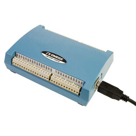
The OM-USB-1208HS, OM-USB-1208HS-2AO and OM-USB-1208HS-4AO are USB 2.0 full-speed voltage input data acquisition modules (fully compatible with both USB 1.1 and USB 2.0 ports). These are stand-alone plug-and-play modules which draw power from the USB cable† “ no external power supply is required. All configurable options (including individual channel ranges) are software programmable, and the modules are fully software calibrated. All three OM-USB-1208HS modules provide 13-bit resolution, and 4 differential or 8 single-ended analog inputs. These modules support software programmable ranges from ±5 to ±20V in a differential configuration, and ±2.5 to ±10V, and 0 to 10V in a single-ended configuration. In software-paced mode, these modules can sample at a maximum of 4 kS/s. In hardwarepaced mode, they can sample at a maximum of 1 MS/s. The OM-USB-1208HS-2AO provides two 12-bit analog outputs, and the USB-1208HS-4AO provides four 12-bit analog outputs.
Both modules offer an output range of ±10V. Analog outputs update at a maximum rate of 5 kS/s in softwarepaced mode; in hardware-paced mode, each analog output updates at a maximum rate of 1 MS/s. On these modules, 16 digital I/O can be programmed on each individual bit as either inputs or outputs. Each module supports two 32-bit TTL-level counters that accept frequency inputs of up to 20 MHz. The packaging for the OM-USB-1208HS, OM-USB-1208HS-2AO and OM-USB-1208HS-4AO ensures ease of use in a variety of applications. The modules can easily be DIN-rail mounted for rack applications.
The OM-USB-1208HS, OM-USB-1208HS-2AO and OM-USB-1208HS-4AO modules ship with an impressive array of software, including the new TracerDAQ®, a full-featured, out-of-the-box data logging, viewing, and analysis application. Driver support and detailed example programs are included for Universal Library programming libraries for Microsoft® Visual Studio® programming languages, and other languages, including DASYLab®, and ULx for NI LabVIEW® (comprehensive library of VIs and example programs compatible with 32-bit and 64-bit LabVIEW v8.5 through 2012) and InstaCalTM installation, calibration and test utility-powerful solutions for programmers and nonprogrammers alike. These modules operate under Microsoft Windows® XP (32-bit only) and VISTA/7/8 (32-bit and 64-bit) operating systems.
The OM-USB-1208HS, OM-USB-1208HS-2AO and OM-USB-1208HS-4AO data acquisition modules are supplied with TracerDAQ software which is a collection of four virtual instrument applications used to graphically display and store input data and generate output signals:
• Strip Chart—Log and graph values acquire from analog inputs,
digital inputs, temperature inputs and counter inputs
• Oscilloscope—Display values acquired from analog inputs
• Function Generator—Generate waveforms for analog outputs
• Rate Generator—Generate waveforms for counter outputs
TracerDAQ PRO is an enhanced version of TracerDAQ. A comparison
of some of the feature included in TracerDAQ vs TracerDQ PRO is shown on the PDF.
SPECIFICATIONS
ANALOG INPUT
A/D Converter: Successive approximation type
Input Ranges: Software selectable per channel
Differential: ±20V, ±10V, ±5V (the voltage level on each
individual AIN input is limited to ±14V)
Single Ended: ±10V, ±5V, ±2.5V, 0 to 10V
Number of Channels:
4 differential/8 single-ended (software-selectable)
Input Configuration: Multiplexed
Channel Gain Queue: 8 unique consecutive elements,
software-configurable range for each channel
Absolute Maximum Input Voltage: CHx IN to GND
Power On: ±25V max
Power Off: ±12V max
Input Impedance: 35 M? min.
Input Bandwidth (-3 dB): All input ranges, 2 MHz typ
Input Leakage Current: ±250 nA typ
Input Capacitance: 32 pf typ
Maximum Working Voltage: (Signal + Common Mode)
±20V: ±14V, ±10V: ±11V, ±5V: ±5.5V
Sampling Rate: 1 S/s to 1 MS/s, software programmable
Sample Clock Source: Internal A/D clock or AICKI
Burst Mode: Software-selectable, burst rate = 1 µs
Throughput
Software-Paced: 33 to 4000 S/s typ, system-dependent
Hardware-Paced: 1 MS/s max
Resolution: 13-bits
A/D No Missing Codes (Uncalibrated)
Differential (Mode): 13-bits
Single Ended (Mode): 12-bits
CMRR: 60 Hz, 74 dB typ
ANALOG OUTPUT
D/A Converter: Texas Instruments DAC7553
Number of Channels: 4 independent
Resolution: 12-bits
Output Range
Calibrated: ±10V
Uncalibrated: ±10.2V
D/A Update Rate
Software Paced: 33 to 5000 S/s typ, system dependent
Hardware Paced: 1 MHz max (per channel)
Sample Clock Source: Internal D/A clock or AOCKI (AO external clock input pin)
Monotonicity: 12-bits
Output Current: ±3 mA max per channel
Power Up and Reset State: 0V
Output Noise: 0.53 mV rms
Absolute Accuracy: ±0.1%
Slew Rate: 6.7V/ µs typ
DIGITAL I/O
Digital Type: CMOS
Number of I/O: 16
Configuration: Each bit may be configured as input
(power on default) or output
Pull-Up Configuration:
The port has 47 k? resistors configurable as pull-ups or pull-downs
by an internal jumper (default setting is pull-down)
Digital I/O Transfer Rate (System Paced): 33 to 8000 port reads/writes
or single-bit reads/writes per second typ, system dependent.
Input High Voltage: 2.0V min, 5.5V absolute max
Input Low Voltage: 0.8V max, -0.5V absolute min, 0V recommended min
Output High Voltage: 4.4V min (IOH = -50 µA), 3.76V min (IOH = -24 mA)
Output Low Voltage: 0.1V max (IOL = 50 µA), 0.44V max (IOL = 24 mA)
Output Current: ±24 mA max per terminal
EXTERNAL TRIGGER
Trigger Source: TRIG input
Trigger Mode: Software configurable for edge- or level-sensitive,
rising or falling edge, high or low level. Power on default is edge sensitive, rising edge.
Trigger Latency: 1 µs + 1 clock cycle max
Trigger Pulse Width: 100 ns min
Input Type: Schmitt trigger, 33 ? series resistor and 47 k? pull-down to ground
Schmitt Trigger Hysteresis: 0.4 to 1.2V
Input High Voltage: 2.2V min, 5.5V absolute max
Input Low Voltage: 1.5V max, -0.5V absolute min, 0V recommended min
EXTERNAL ACQUISITION
SCAN CLOCK I/O
Terminal Names:
AICKI, AICKO, AOCKI, AOCKO
Terminal Types
AxCKI: Input, active on rising edge
AxCKO: Output, power on default is 0V, active on rising edge
Terminal Descriptions
AxCKI: Receives sampling clock from external source
AxCKO: Outputs internal sampling clock (D/A or A/D clock)
or pulse generated from AxCKI when in external clock mode
Input Clock Rate: 1 MHz max
Clock Pulse Width
AxCKI: 400 ns min
AxCKO: 400 ns min
Input Type: Schmitt trigger, 33 ? series resistor, 47 k? pull-down to ground
Schmitt Trigger Hysteresis: 0.4 to 1.2V
Input High Voltage: 2.2V min, 5.5 V absolute max
Input Low Voltage: 1.5V max, -0.5V absolute min, 0V recommended min
Output High Voltage: 4.4V min (IOH = -50 µA), 3.76V min (IOH = -24 mA)
Output Low Voltage: 0.1V max (IOL = 50 µA), 0.44V max (IOL = 24 mA)
Output Current: ±24 mA max per terminal
COUNTERS
Counter Terminal Names: CTR0, CTR1
Counter Type: Event counter
Number of Channels: 2
Input Type: Schmitt trigger, 33 ? series resistor, 47 k? pull-down to ground
Schmitt Trigger Hysteresis: 0.4 to 1.2V
Input High Voltage: 2.2V min, 5.5V absolute max
Input Low Voltage: 1.5V max, -0.5V absolute min, 0V recommended min
Resolution: 32-bits
Max Input Frequency: 20 MHz
Counter Read/Write Rates (Software Paced): 33 to 8000
reads/writes per second typ, system dependent
High Pulse Width: 25 ns min
Low Pulse Width: 25 ns min
TIMER
Timer Terminal Name: TMR
Timer Type: PWM output with count, period, delay, and pulse width registers
Output Value: Default state is idle low with pulses high, software-selectable output invert
Internal Clock Frequency: 40 MHz
Register Widths: 32-bits
High Pulse Width: 20 ns min
Low Pulse Width: 20 ns min
Output High Voltage: 4.4V min (IOH = -50 µA), 3.76V min (IOH = -24 mA)
Output Low Voltage: 0.1V max (IOL = 50 µA), 0.44V max (IOL = 24 mA)
Output Current: ±24 mA max per pin
MEMORY
Data FIFO: 4 kS analog input/4 kS analog output
Non-Volatile Memory: 32 KB (16 KB firmware storage, 16 KB calibration/user data)
POWER
Operating Modes: Bus-powered, USB 5V supply
Supply Current: Total current consumption including 5V,
and digital output and analog output currents
Suspend Mode: <2.5 mA
Enumeration: <100 mA
Run Mode: <500 mA
Power Consumption Excluding Analog and Digital Outputs
Run Mode: 1.175 W max (235 mA input current)
Power Available for 5V, AICKO, AOCKO, TMR, Analog Outputs,
Digital I/O:
Run Mode: 1.325 W max
+5 V Output Voltage Range:
Run Mode: 4.5V min, 5.25V max
Suspend Mode, Enumeration: 0V
+5V Output Current (Run Mode,
No Other Output Loads): 265 mA max (1.325 W)
USB SPECIFICATIONS
USB Device Type: USB 2.0 (high-speed)
USB Device Compatibility: USB 1.1, 2.0
USB Cable Length: 5 m (16.4') max
GENERAL
Operating Temperature Range: 0 to 50°C (32 to 122°F)
Storage Temperature Range: -40 to 85°C (-40 to 185°F)
Humidity: 0 to 90% RH non-condensing
Communications: USB 2.0 (high-speed)
Acquisition Data Buffer: 4 kS
Signal I/O Connector: 2 banks of screw-terminal blocks
Dimensions: 79 L x 82 W x 25 mm H (3.11 x 3.23 x 0.98")
Weight: 160 g (0.35 lbs)
PDFs & Manuals
Software & Drivers