1-800-663-4209 | Your feedback matters, take a quick survey Website Feedback
DRST-UN-Univ-Sig-Cond
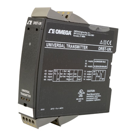
DIN Rail Universal Programmable Input Signal Conditioner
Models In Stock
- Input for RTD, TC, O, potentiometer, mA and V
- 2-wire supply 16 V
- UL and cUL Approval
- Output for current and voltage
DRST-UN-Univ-Sig-Cond
From
C$
347.84
Models In Stock
Product Overview
- Accuracy ± 0.1 %
- Approvals UL: UL 508/C22.2 no. 14; NV-GL Marine Stand. f. Certific. No. 2.4; EU RO Mutual Recognition Type; Approval: MRA000000Z; SIL Hardware assessed for use in SIL applications; Authority Requirements:EMC: 2014/30/EU, LVD: 2014/35/EU, EAC: TR-CU 020/2011
- Calibration Temperature, Max 28 °C
- Calibration Temperature, Min 20 °C
- Cold Junction Compensation 20 to 28°C = ±1°C, -20 to 20°C/28 to 70°C = 2°C
- Electrical Output 0 to 20 mA, 0 to 10 Vdc
- EMC Immunity Note Standard EMC Imunity: <±0.5% of span; Extended EMC Immunity: NAMUR, NE21, A Criterion, Burst: <±1% of span; Wire Size: 1 x 2.5 mm²
- EMC Standard EN61010-1, EN61326-1
- Enclosure Ratings IP20
- Fuse Rating 250 Vac/400 mA
- Height 109 mm
- Input Control Signal 0 to 12 Vdc
- Input Control Signal Note Measurement Range: 0 to 12 Vdc; Programmable Measurement Ranges: 0/0.2 to 1, 0/1 to 5, 0/2 to 10 Vdc
- Input Current 0 to 20 mA
- Input_Current Note Programmable Measurement Ranges: 0 to 20 and 4 to 20 mA; Input Resistance: Nom. 20 Ω + PTC 50 Ω Sensor Error Detection: Loop; Break 4 to 20 mA: Yes
- Input Resistance Voltage : Nom. 10 MΩ, Current: Nom. 20 Ω + PTC 50 Ω
- Isolation Test/Working: 2.3 kVac/250Vac
- Length 104 mm
- Operating Temperature, Max 60 °C
- Operating Temperature, Min -20 °C
- Output Detail Signal Range: 0 to 20 mA; Programmable Signal Ranges: 0 to 20/4 to 20/20 to 0/20 to 4 mA; NAMUR NE43 Upscale/Downscale: 23 mA/3.5 mA; Output Limitation, on 4 to 20 and 20 to 4 mA signals: 3.8 to 20.5 mA; Output Limitation, on 0 to 20 and 20 to 0 mA signals: 0 to 20.5 mA; Signal Range: 0 to 10 Vdc; Programmable Signal Ranges: 0/0.2 to 1; 0/1 to 5 ; 0/2 to 10; 1 to 0.2/0; 5 to 1/0; 10 to 2/0 V
- Output Signal Current, Voltage
- Potentiometer Input Range 10 to 100 kΩ
- Power Consumption 2 W
- Relative Humidity < 95% RH Non-Condensing
- Response Time 1 sec
- Response Time Note Thermocouple: 1 sec, Current/Voltage: 400msec
- RTD Input Note Effect of Sensor Cable Resistance: < 0.002 Ω/Ω (3/4-wire); Cable Resistance, Per Wire: 50 Ω; Sensor Current: 0.2 mA; Short Circuit Protection: < 15 Ω; Sensor Error Current: 2 µA / 0 µA
- RTD Type 10/20/50/100/200/250/300/400/500/1000 Ω Pt Sensor, 50/100/120/1000 Ω Ni Sensor, 10/20/50/100 Ω Cu Sensor
- Screw Terminal Torque 0.5 Nm
- Sensor/Transmitter Power 5 to 16 Vdc/0 to 20 mA
- Signal/Noise Ratio > 60 dB
- Storage Temperature, Max 85 °C
- Storage Temperature, Min -20 °C
- Supply Power Note 21.6 to 253 Vac, 50 to 60 Hz or 19.2 to 300 Vdc
- Supply Power Type AC/DC
- Supply Voltage 21.6 to 253 Vac, 19.2 to 300 Vdc
- Temperature Coefficient ≤±0.01% of span/°C
- Temperature Measurement Range J: -100 to 1200°C, K: -180 to 1370 °C, T: -200 to 400 °C, E: -100 to 1000 °C, R: -50 to 1760 °C, S: -50 to 1760 °C, N: -180 to 1300 °C, B: 0 to 1820 °C, W3: 0 to 2300 °C, W5: 0 to 2300 °C, L: -200 to 900 °C, LR: -200 to 800 °C, RTD: -200 to 850 °C
- Thermocouple Type J, K, T, E, R, S, B, C, N, L, U, D, LR
- Vibration ±0.7 g
- Vibration Note IEC 60068-2-6; 2 to 13.2 Hz: ±1 mm; 13.2 to 100 Hz: ±0.7 g
- Weight 145 g
- Width 23.5 mm
- Wire Type Stranded
Advanced Features
Programmable by way of detachable display front, process calibration, signal simulation, password protection, error diagnostics and help text available in several languages.
Application
• Linearized, electronic temperature measurement with RTD or TC sensor.
• Conversion of linear resistance variation to a standard analog current / voltage signal, i.e. from solenoids and butterfly valves or linear movements with attached potentiometer.
• Power supply and signal isolator for 2-wire transmitters.
• Process control with standard analog output. Galvanic separation of analog signals and measurement of floating signals.
• The DRST-UN is designed according to strict safety requirements and is therefore suitable for application in SIL 2 installations.
Technical Characteristics
• When DRST-UN is used with the DRSL-DISPLAY programming front, all operational parameters can be modified to suit any application. As the DRST-UN is designed with electronic hardware switches, it is not necessary to open the device for setting of DIP-switches.
• A green / red front LED indicates normal operation and malfunction.
• Continuous check of vital stored data for safety reasons.
• 3-port 2.3 kVAC galvanic isolation.
Specifications
Environmental Conditions
Operating Temperature: -20 to 60 °C
Storage Temperature: -20 to 85 °C
Calibration Temperature: 20 to 28 °C
Relative Humidity: < 95% RH (non-cond.)
Protection Degree:v IP20
Mechanical Specifications
Dimensions (H x W x D): 109 x 23.5 x 104 mm
Weight Approx: 145 g
Wire Size: 1 x 2.5 mm 2 stranded wire
Screw Terminal Torque: 0.5 Nm
Vibration: IEC 60068-2-6
2 to 13.2 Hz: ±1 mm
13.2 to 100 Hz: ±0.7 g
Common Specifications
Supply
Supply Voltage, Universal:21.6 to 253 Vac, 50 to 60 Hz or 19.2 to 300 Vdc
Fuse: 400 mA SB/250 Vac
Max. Required Power: = 2.0 W
Isolation Voltage Isolation voltage, test/working:2.3 k Vac / 250 Vac
Response Time
Temperature input (0 to 90%, 100 to 10%): = 1 s
mA / V input (0...90%, 100...10%): = 400 ms
Auxiliary Supplies
2-w. supply (term. 44 to 43): 5 to 16 Vdc/0 to 20 mA
Programming: Communication enabler DRSL-DISPLAY
Signal/Noise Ratio: Min. 60 dB (0 to 100 kHz)
Accuracy: Better than 0.1% of sel. range
EMC Immunity Influence: < ±0.5% of span
Extended EMC Immunity: NAMUR
NE21, A Criterion, Burst: < ±1% of span
Input Specifications
RTD Input
RTD Type:
Pt10/20/50/100/200/250;
Pt300/400/500/1000;
Ni50/100/120/1000;
Cu10/20/50/100
Cable Resistance Per Wire: 50 Ω (max.)
Sensor Current: Nom. 0.2 mA
Effect of Sensor Cable Resistance (3/4-wire): < 0.002 Ω/Ω
Sensor Error Detection: Yes
Short Circuit Detection < 15 Ω
Linear Resistance Input
Linear Resistance Min/Max: 0 to 10000 Ω
Potentiometer Input
Potentiometer Min/Max: 10 to 100 kΩ
TC Input
Thermocouple Type: B, E, J, K, L, N, R, S, T, U, W3, W5, LR
Cold Junction Compensation (CJC) via ext. Sensor in Connector 5910: 20 to 28 °C = ±1 °C, -20 to 20 °C/28 to 70 °C = 2 °C
CJC via int. Mounted Sensor: ±(2.0 °C + 0.4 °C * Δt)
Δt =: Internal temp.-ambient temp.
Sensor Error Detection: Yes
Sensor Error Current: When detecting/else: Nom. 2 µA / 0 µA
Current Input
Measurement Range: 0 to 20 mA
Programmable Measurement Ranges: 0 to 20 and 4 to 20 mA
Input Resistance: Nom. 20 Ω + PTC 50 Ω Sensor Error Detection: Loop
Break 4 to 20 mA: Yes
Voltage Input
Measurement Range: 0 to 12 Vdc
Programmable Measurement Ranges: 0/0.2 to 1, 0/1 to 5, 0/2 to 10 Vdc
Input Resistance: Nom. 10 MΩ
Output Specifications
Current Output
Signal Range: 0 to 20 mA
Programmable Signal Ranges: 0 to 20/4 to 20/20 to 0/20 to 4 mA
Load (@ current output): = 800 Ω
Load stability: = 0.01% of span / 100 Ω
Sensor Error Indication: 0/3.5/23 mA/none
NAMUR NE43 Upscale/Downscale: 23 mA/3.5 mA
Output Limitation, on 4 to 20 and 20 to 4 mA signals: 3.8 to 20.5 mA
Output Limitation, on 0 to 20 and 20 to 0 mA signals: 0 to 20.5 mA
Current Limit: = 28 mA
Voltage Output
Signal Range: 0 to 10 Vdc
Programmable Signal Ranges: 0/0.2 to 1; 0/1 to 5 ; 0/2 to 10; 1 to 0.2/0; 5 to 1/0; 10 to 2/0 V
Load (@ Voltage Output): = 500 kΩ
Of span: = of the currently selected measurement range
Observed Authority Requirements
EMC: 2014/30/EU
LVD: 2014/35/EU
EAC: TR-CU 020/2011
Approvals
UL UL 508 / C22.2 no. 14
DNV-GL Marine Stand. f. Certific. No. 2.4 EU RO Mutual Recognition Type
Approval:MRA000000Z
SIL: Hardware assessed for use in SIL applications
PDFs & Manuals
Accessories
Show Ratings & Reviews
Rated 5 out of
5
by
MRIM from
Omega Order - RI
Great service by omega, fast shipping. The module was able to grab a signal off of our power instrumentation to clean the signal and give us a reliable output.
Date published: 2022-11-10
Rated 5 out of
5
by
Jordan23 from
good product
good product, works as it should, ordereed it and had it when needed
Date published: 2022-08-05
Is the Display required to configure the unit? Out of the box, output is saturated high with a low voltage input.
Thank you for your question. Thank you for your question. Yes, the DRSL-DISPLAY is required to configure the conditioner.
https://www.omega.com/en-us/data-acquisition/signal-conditioners/din-rail-signal-conditioners/drsl-display-programmer/p/DRSL-DISPLAY?searchterm=DRSL-DI
Date published: 2024-02-27
Is the output of this device single-ended or differential?
Thank you for your question. The output is single-ended.
Date published: 2023-01-10
Will this do a 0-30VAC input signal? It doesn't specify AC or DC when mentioning Voltage input
Thank you for your question. This will only support DC voltage up to 10 volts. Please review DR-I4E which is programmable for AC and DC voltage.
https://www.omega.com/en-us/data-acquisition/signal-conditioners/din-rail-signal-conditioners/dr-i4-series/p/DR-I4E
Date published: 2024-12-07
Can the upper and lower measuring range be programmed, eg. 55deg F = 4ma, 125deg F = 20ma ?
Hello, thank you for your question. Yes, you would use the DRSL-DISPLAY (sold separately) to program the scale according to the desired input and output.
Date published: 2024-02-27
In Simulation mode EN.SIM. Can an input value be set permanently (like simulating a thermocouple at 700deg C) to have a permanent steady constant output mA or Volts?
Thank you for your question. We will require more information to help on this question, please email the DAS team at DAS@dwyeromega.com
Date published: 2024-08-27