1-800-663-4209 | Your feedback matters, take a quick survey Website Feedback
OM-NET-TC
Choose a Variant
Output Signal
Volume discounts available
Volume Discount Schedule
| Quantity | Price each |
|---|---|
| 1-4 | C$876.38 |
| 5-9 | C$832.56 |
| 10-24 | C$815.03 |
| 25-49 | C$779.98 |
| 50-99 | C$762.45 |
| 100+ | C$744.92 |
Product Specs
<< See all Product Models| Brand |
|
| Accuracy | ± 0.006% |
| Alarm Note | Number of Alarms: 8 (one per digital I/O line)
Alarm Functionality: Each alarm controls its associated digital I/O line as an alarm output. When an alarm is enabled, its associated I/O line is set to output and driven to the appropriate state determined by the alarm options and input temperature. The alarm configurations are stored in non-volatile memory and loaded at power on
Alarm Input Modes:
• Alarm when input temperature ≥T1, reset alarm when input temperature |
| Analog I/O Note | Analog Input Note: THERMOCOUPLE INPUT ;A/D Converter Type: Delta-Sigma;A/D Resolution: 24-bit;Number of Channels: 8 differential channels;Isolation Between Any Thermocouple Input Channel and Digital/Chassis Ground: 500 Vdc absolute max;Channel Configuration: Software selectable for thermocouple types J, K, T, E, R, S, B, N (factory default configuration is type J). Channel configuration is stored on EEPROM external to the isolated microcontroller by the firmware whenever any item is modified. Modification is performed by commands issued from an external application, and the configuration is made non-volatile through the use of the EEPROM.;Differential Input Voltage Range: ±0.128V (calibration is performed at ±70 mV);Absolute Maximum Input Voltage (Between any Two TCx Inputs): ±25V (power on), ±25V (power off);Differential Input Impedance: 40 MΩ;Input Current; Open Thermocouple Detect ;Disabled: 1 nA; Open Thermocouple Detect ;Enabled: 65 nA;Common Mode Rejection (fin = 50 Hz or 60 Hz): 110 dB;Noise Rejection (fin = 50 Hz or 60 Hz): 75 dB;Input Bandwidth: 10 Hz;Crosstalk Between Any Two Thermocouple Inputs: -90 dB;Sample Rate: 4 Hz max (per channel). The enabled thermocouple inputs are continuously converted at the maximum A/D converter rate. If channels are enabled and have an open thermocouple connection the sampling rate will be lower.;Input Noise: 250 nV rms;Gain Error: 0.006% FSR;Offset Error: 3 μV;Measurement Sensitivity (Smallest Change in Temperature That Can Be Detected): ;Thermocouple Type J,K,T,E,N: 0.09°C;Thermocouple Type R,S: 0.11°C;Thermocouple Type B: 0.13°C;Warm-Up Time: 20 minutes min;Open Thermocouple Detect Response Time: 1 s;CJC Sensor Accuracy (0 to 45°C): ±0.20°C typ, ±0.40°C max; |
| Bandwidth | 10 Hz |
| CMRR | 110 dB |
| Configuration Parameters | EEPROM Configuration Storage, Thermocouple Type Selection, User-Configurable Input/Output |
| Data Interface | Ethernet |
| Data Interface Note | Ethernet Type - 100 Base-TX, 10 Base-T;Protocols Used: TCP/IP (IPv4 only), UDP;Network Ports Used: UDP:54211 (discovery), UDP:6234 (bootloader only), TCP:54211 (com¬mands);Network IP Configuration: DHCP + link local, DHCP, static, link-local ;Network Name: E-TC-xxxxxx, where xxxxxx are the lower 6 digits of the device MAC address;Network Name Publication: By NBNS (responds to b-node broadcasts, therefore only available on the local subnet);Ethernet: 10/100 Mbps, auto-negotiated;Network Factory Default Settings;"Factory Default IP Address: 192.168.0.101;Factory Default Subnet Mask: 255.255.255.0 ;Factory Default Gateway: 192.168.0.1;Factory Default DHCP Setting: DHCP + link-local enabled";Network Security;"Security Implementation: TCP sockets are not opened unless application sends the correct PIN code (stored in non-volatile memory, may be changed by user, default value 0000);Number of Concurrent Sessions: 1;Vulnerabilities: TCP sequence number approximation vulnerability";Factory Reset Button;Used to reset the network configuration settings to the factory default values;Ethernet Cable Length, Max: 100 m;Configuration Method: Independently configured |
| Digital I/O Note | DIGITAL I/O Digital Type: 5V TTL input/ CMOS output Number of I/O: One port of 8 bits, shared with temperature alarms Configuration: Each bit can be independently configured for input or output Pull-Up Configuration: All pins pulled up to 5V using 47 K resistors (default). Can be changed to pull-down using an internal jumper Digital I/O Transfer Rate (System Paced): 100 to 5000 port reads/writes or single bit reads/writes per second typ, on local network. This is the typical throughput when the device and host are both connected by Ethernet to the same local network. The throughput can vary significantly, and typical throughput is not guaranteed if a wireless connection is involved or data is sent over the internet Alarm Functionality: Any combination of DIO bits may be configured to become outputs and go to defined values when an Ethernet connection with a host is established or lost Power On and Reset State: All bits are input unless the alarm functionality is enabled for them Input High Voltage Threshold: 2.0V min Input High Voltage Limit: 5.5V absolute max Input Low Voltage Threshold: 0.8V max Input Low Voltage Limit: -0.5V absolute min, 0 V recommended min Output High Voltage: 4.4V min (IOH = -50 µA), 3.76V min (IOH = -24 µA) Output Low Voltage: 0.1V max (IOL = 50 µA), 0.44V max (IOL = 24 µA) Power On and Reset State: Input;Cross talk: -90 db;Schmitt Trigger Hysteresis: 0.6V min, 1.7V max |
| Digital Input | Digital: Low = –0.5 Vdc |
| Digital Output | 10 mA max |
| Electrical Connection | Screw Terminal |
| Frequency Input Range | 10 MHz |
| Height | 29 mm |
| Input Configuration | Connected Software |
| Input Type | Thermocouple, Digital |
| Input Type Note | Thermocouple: J, K, T, E, R, S, B, N |
| Input Voltage Note | Absolute Maximum Input Voltage: ±25V (Power On), ±25V (Power Off) |
| Isolation | Isolation Between Any Thermocouple Input Channel and Digital/Chassis Ground: 500 Vdc absolute max |
| LED Indicators | Power LED (Top),Activity LED (Bottom),Ethernet Connector LEDs Left, Green: Link/activity indicator |
| Length | 117.9 mm |
| Memory | EEPROM: 4096 bytes |
| NMRR | 75 dB |
| Number of Channels, Input | Thermocouple: 8 DIFF, Digital: 1, Temperature Alarms: 8, Counter: 1 |
| Number of Channels, Output | Digital: 1, Temperature Alarms: 8 |
| Operating Temperature, Max | 55 °C |
| Operating Temperature, Min | 0 °C |
| Output Resolution | Digital: 8-bits, Temperature Alarms: 8 |
| Output Signal | Digital, Alarm |
| Pull-down Resistor | 47 kΩ, GND |
| Pull-up Resistor | 47 kΩ |
| Relative Humidity | 0 to 90% RH non-condensing |
| Sampling Rate | 4 Hz (4 updates/second) |
| Sampling Rate Note | 4 Hz max (per channel). The enabled thermocouple inputs are continuously converted at the maximum A/D converter rate. If channels are enabled and have an open thermocouple connection the sampling rate will be lower. |
| Storage Temperature, Max | 85 °C |
| Storage Temperature, Min | -40 °C |
| Supply Current | 177 mA |
| Supply Power Note | External Power Supply: 5V, 1A (via included AC adapter) Supply Current (Quiescent Current): 177 mA typ (this is the total quiescent current requirement for the device that includes the LEDs and does not include any potential loading of the digital I/O bits or +VO terminal User Output Voltage Range (Available at +VO Terminal): 4.40V min to 5.25V max, assumes supplied AC adapter is used User Output Current (Available at +VO Terminal): 10 mA max |
| Supply Voltage | 5 Vdc |
| Warm Up Time | 20 min |
| Weight | 0.4 kg |
| Width | 82.8 mm |
| Wire Gauge | 30 to 16 AWG |
| See All Specs | |
PDFs & Manuals
Software & Drivers
Show Ratings & Reviews
Rated 4 out of
5
by
Robert2 from
Good Hardware - Good Price - Software Not So Good
The Omega hardware has proven itself to be reliable and well developed. I wish there was at least one more
set of software support possibilities that would support their hardware better than the InstaCal/TracerDaqPro combination.
The software is not user friendly. Depending on how you move thru the programs, you can easily lose data. It is very sensitive
to the sequence that you add/change data that is pertinent to both applications. Lastly, the application restricts thermocouple
support to 48 channels. There should be an alternative selection/or software that supports more than 48 channels.
Date published: 2019-04-08
Rated 1 out of
5
by
researchreactor from
Works but label was rotated
Same issue as the other 2 reviews: got an "open connection" error when trying to test the analog inputs, and when I rotated the connections 180 degrees the error went away. Very annoyed at Omega.
Date published: 2018-11-09
Rated 3 out of
5
by
jdbos from
Works but connector label is applied wrong
I had the same experience as reviewer Clearw. However, I discovered the problem - the I/O label is rotated 180°. Just mentally rotate the label so that CH0H is at the front right and CH7L at the rear right when you look at the device from the end with the power connector.
The attached photo shows the device hooked up to working thermocouples. As you can see, the TC wires are on the connector block on the right when you hold the power connector toward you.
Once you do this, the device works fine, at least the TC inputs. Presumably the connector block on the left has the digital I/O etc. but I didn't check that out.
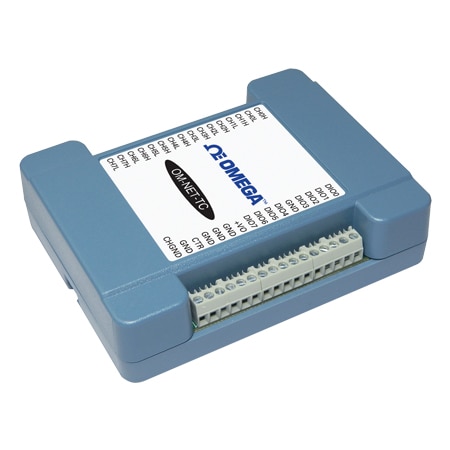
The photo of the device on the Omega website actually shows the label affixed correctly - although I only discovered that after I had figured out the problem from other clues. (It did not make sense that the jumper for the digital PU/PD option was on the opposite side of the circuit board from the digital I/O, and when you look at the circuit board, the connections labeled for differing functions all appeared to have identical board topology, which is what you would expect for the TC inputs.)
This should be embarrassing for Omega. They have had a month since Clearw posted his review and they haven't posted a correction. Their own photo on their website is different from the device I received, so somebody there has realized it but not told the service department.
Date published: 2018-09-08
Rated 1 out of
5
by
Clearw from
Engineer
Did not work correctly right out of the package. "open connection" error messages.
Date published: 2018-08-06