1-800-663-4209 | Your feedback matters, take a quick survey Website Feedback
HBM-M-Linear
Linear Strain Gauges for High Temps & Alternating Load Resistance
- High Resistance to Alternating Loads
- High Temperature Range 300°C (572°F)
- Wide Spectrum of Different Types
- All models sold in a 5-pack, except 1-LM11 which are sold in a 10-pack
HBM-M-Linear
From
C$
305.30
Product Overview
- Bend Radius, Min 5 mm
- Carrier Thickness 35 μm
- Electrical Connection Solder Pads
- Elongation 10000 µm to 15000 µm
- Encapsulation Thickness 25 μm
- Gauge Factor 2.2
- Grid Style Linear
- Grid Thickness 5 μm
- Materials Glass reinforced phenolic, Chromium-Nickel, Polyimide
- Mechanical Life 10⁷ cycles
- Mechanical Life Note 10⁷ cycles at 2000 µm/m, 10⁶ cycles at 2200 µm/m, 10⁴ cycles at 3100 µm/m
- Nominal Resistance 350 Ω
- Operating Temperature, Max 300 °C
- Operating Temperature, Min -200 °C
- Pack Size 10
- Resistance Tolerance ±0.3%
- Temperature Compensation 10.8 ppm/K
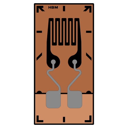
Linear Pattern Strain Gages are the most straightforward geometry of strain gauge, designed to indicate strain in only a single direction.
M Series strain gauges have been specially developed for high resistance to alternating loads at increased strain levels and high temperatures up to 300°C (572°F). They are foil strain gauges with measuring grids made of a special nickel-chromium alloy. OMEGA/HBM offer this special strain gauge with various geometries, measuring grid lengths and temperature response matching.
New materials offering high strength such as fiber composites pose a major challenge for strain gauges used for measurements specifically when pushing components to their mechanical limit of performance. Situations may arise where a strain gauge subjected to alternating loads at increased load levels is weakened and fails earlier than the component under test. The M Series has been specially developed for high resistance to alternating loads and allows for testing of materials featuring high strength.
All M Series strain gauge types are available with different measuring grid lengths:
• 1.5 mm: where space is a constraint or when highly selective measurement results are required
• 3 mm: for inhomogeneous materials and where space is a requirement or not
• 6 mm: for inhomogeneous materials and where space is not a requirement
The right measuring grid length: The measuring grid length depends on the aim of measurement, since the result of a measurement with strain gauges will be determined as the average of strains. In general, measuring grid lengths of 3 to 6 mm (0.06 to 0.24') generates a better result.
Long measuring grids are recommended where there is an inhomogeneous material such as concrete or wood. A long strain gauge will bridge the inhomogeneity of the work piece and return the strain underneath the measuring grid as the measurement result.
Short measuring grids are suitable for detecting a local strain state. Therefore, they are suitable for determining strain gradients, the maximum point of notch stresses and similar stresses.
Specifications
Strain Gage Construction–Foil Strain Gauge
Carrier:
Material: Glass fiber reinforced phenolic
Thickness: 35 ±10 µm
Grid Foil:
Material: CrNi
Thickness: 5 µm
Encapsulation:
Material: Polyimide film
Thickness: 25 ±5 µm
Connections: Solder pads with strain relief
Resistance: 350 and 1000 Ω
Resistance Tolerance: ±0.3%(1)
Gage Factor: Approximate 2.2 (specified on each package)
Gage Factor Tolerance: ±1.5% (for grid length <3 mm) ±0.7% (for grid length ≥3 mm)
Temperature Coefficient of the Gauge Factor: Specified on each package
Transverse Sensitivity: Specified on each package
Operating Temperature Range: -200 to 300°C (-328 to 662°F)
Temperature Response (Ferrite Steel): 10.8 ppm/K (6.0 ppm/°F)
Maximum Elongation:
Positive Direction: 10,000 µm (1%)
Negative Direction: 15,000 µm (-1.5%)
Minimum Bending Radius: 5 mm (0.20') for linear gauges 10 mm (0.39') for stacked rosettes
Bonding Material that Can Be Used: Z70 or EP310S
Fatigue Life (Test to Failure):
107 cycles at 2000 µm/m
106 cycles at 2200 µm/m
104 cycles at 3100 µm/m
PDFs & Manuals