1-800-663-4209 | Vos commentaires sont importants, répondez à un sondage rapide commentaires sur le site web
SSRL240-660
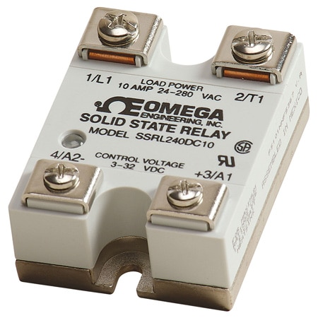
Solid State Relays with AC or DC Control Inputs
Modèles en stock
- Current Ratings to 100 Amps
- Multi-Million Cycle Life
- Compatible with Temperature Controllers
- Solid-State, SCR Design
SSRL240-660
Depuis
C$
51.45
Modèles en stock
L'aperçu du produit
- Current Draw 100 mA
- Features High Reliability
- Frequency 47 to 63 Hz
- Input/Output-to-Ground Isolation 2500 Vrms
- Input-to-Output Capacitance 8 pF
- Isolated Analog Voltage 4000 Vrms
- Number of Phases 1
- Operating Temperature, Max 80 °C
- Operating Temperature, Min -20 °C
- Operating Voltage, Min 1.6 V
- Storage Temperature, Max 80 °C
- Storage Temperature, Min -40 °C
- Surge Current Rating 1 Cycle, Max: 150 A; 1 s, Max: 30 A
- Thermal Sensitivity 416
The Omega's SSRL series of solid state relays are used to control large resistance heaters in conjunction with temperature controllers. Solid state relays are SPST, normally open switching devices with no moving parts, capable of millions of cycles of operation. By applying a control signal, an SSR switches ON the ac load current, just as the moving contacts do on a mechanical contactor. Three-phase loads can be controlled using 2 or 3 SSRs. Use 3 SSRs for Y or star 3-phase loads using a neutral line. Two SSRs will control † œdelta† loads with no neutral line. Three solid state relays are also used when there is no neutral load to provide redundancy and extra assurance of control.
'Switching' takes place at the zero voltage crossover point of the alternating current cycle. Because of this, no appreciable electrical noise is generated, making SSRs ideal for environments where there are apparatuses susceptible to RFI.
Common Specifications
Operating Temperature: -20 to 80 °C (-5 to 175 °F)
Storage Temperature:-40 to 80 °C (-40 to 175 °F)
Isolation: 4000 Vrms, input to output; 2500 Vrms input/output to ground
Capacitance: 8 pF, input to output (max)
Line Frequency Range: 47 to 63 Hz
Turn-On Time: 20 ms, ac; 05 cycle, dc
Turn-Off Time: 30 ms, ac; 05 cycle, dc
These SSRs are of the twin SCR type, inherently more reliable and capable of higher overloads before failure than triacs. Heat is developed in a solid state relay due to the nominal voltage drop across the switching device. To dissipate the heat, an SSR must be mounted on a finned heat sink or aluminum plate. An SSR should be located where the ambient temperature is relatively low, since the current switching rating is lowered as the temperature increases. Another SSR characteristic is a small leakage current across the output when the relay is open. Because of this, a voltage will always exist on the load side of the device.
In comparing SSRs with mechanical contactors, the SSR has a cycle life many times that of a comparably priced contactor. However, SSRs are more prone to failure due to overload and improper initial wiring. Solid state relays can fail, contact closed, on overload circuits. It is essential that a properly rated, fast blowing I2T fuse be installed to protect the load circuit.
Finned heat sinks are anodized fabrications that come complete with tapped mounting holes and screws. See thermal rating curves and ordering instructions for proper selection.
All SSRL series relays come with a thermally conductive pad mounted on the baseplate. This will significantly improve the thermal conductivity between the heat sink and SSR baseplate. It is also suggested that 10-inch-pounds of torque be used on the SSR mounting screws.
![]()
![]()
Output Specifications for Vac and Vdc Input Models
SSR240 Series Electrical Specifications
*Transients above table value should be suppressed.
SSR240 Series Output-Vac Load Specifications
Read More
'Switching' takes place at the zero voltage crossover point of the alternating current cycle. Because of this, no appreciable electrical noise is generated, making SSRs ideal for environments where there are apparatuses susceptible to RFI.
Common Specifications
Operating Temperature: -20 to 80 °C (-5 to 175 °F)
Storage Temperature:-40 to 80 °C (-40 to 175 °F)
Isolation: 4000 Vrms, input to output; 2500 Vrms input/output to ground
Capacitance: 8 pF, input to output (max)
Line Frequency Range: 47 to 63 Hz
Turn-On Time: 20 ms, ac; 05 cycle, dc
Turn-Off Time: 30 ms, ac; 05 cycle, dc
These SSRs are of the twin SCR type, inherently more reliable and capable of higher overloads before failure than triacs. Heat is developed in a solid state relay due to the nominal voltage drop across the switching device. To dissipate the heat, an SSR must be mounted on a finned heat sink or aluminum plate. An SSR should be located where the ambient temperature is relatively low, since the current switching rating is lowered as the temperature increases. Another SSR characteristic is a small leakage current across the output when the relay is open. Because of this, a voltage will always exist on the load side of the device.
In comparing SSRs with mechanical contactors, the SSR has a cycle life many times that of a comparably priced contactor. However, SSRs are more prone to failure due to overload and improper initial wiring. Solid state relays can fail, contact closed, on overload circuits. It is essential that a properly rated, fast blowing I2T fuse be installed to protect the load circuit.
Finned heat sinks are anodized fabrications that come complete with tapped mounting holes and screws. See thermal rating curves and ordering instructions for proper selection.
All SSRL series relays come with a thermally conductive pad mounted on the baseplate. This will significantly improve the thermal conductivity between the heat sink and SSR baseplate. It is also suggested that 10-inch-pounds of torque be used on the SSR mounting screws.
Output Specifications for Vac and Vdc Input Models
| Specifications | 10 Amp | 25 Amp | 50 Amp | 75 Amp | 100 Amp |
| Max On State Current | 10 A | 25 A | 50 A | 75 A | 100 A |
| Max On State Current | 100 mA | ||||
| Max 1-Cycle Surge | 150 A | 300 A | 750 A | 1000 A | 1200 A |
| Max 1 sec Surge | 30 A | 75 A | 150 A | 225 A | 300 A |
| 12T (60 Hz), A2sec | 416 | 937 | 2458 | 5000 | 6000 |
SSR240 Series Electrical Specifications
| Input-Control Signal | Output | |||||
| Model No. | Type | Control Signal Voltage | Control Signal Turn-On | Control Signal Turn-Off | Max Input Current | Peak Voltage* (60 Sec. Max.) |
| SSRL240AC10 SSRL240AC25 SSRL240AC50 SSRL240AC75 SSRL240AC100 | ac Control Signal | 90 to 280 Vac | 90 Vac | 10 Vac | 10 mA | 800 V |
| SSRL240DC10 SSRL240DC25 SSRL240DC50 SSRL240DC75 SSRL240DC100 | dc Control Signal | 3 to 32 Vdc | 3 Vdc | 1 Vdc | 14 mA | 800 V |
| SSRL660AC50 SSRL660AC75 SSRL660AC100 | ac Control Signal | 90 to 280 Vac | 90 Vac | 10 Vac | 10 mA | 1200 V |
| SSRL660DC50 SSRL660DC75 SSRL660DC100 | dc Control Signal | 4 to 32 Vdc | 4 Vdc | 1 Vdc | 14 mA | 1200 V |
SSR240 Series Output-Vac Load Specifications
| Model No. | Nominal ac Line Voltage | Nominal Load Current | Max. Contact Voltage Drop | Max. Off-State Leakage (25 °C max. ambient) | ||
| 120 Vac | 240 Vac | 440 Vac | ||||
| SSRL240AC10 SSRL240AC25 SSRL240AC50 SSRL240AC75 SSRL240AC100 | 24 to 280 Vac | 10 A 25 A 50 A 75 A 100 A | 1.6 V | 0.1 mA | 0.1 mA | N/A |
| SSRL240DC10 SSRL240DC25 SSRL240DC50 SSRL240DC75 SSRL240DC100 | 24 to 280 Vac | 10 A 25 A 50 A 75 A 100 A | 1.6 V | 0.1 mA | 0.1 mA | N/A |
| SSRL660AC50 SSRL660AC75 SSRL660AC100 | 48 to 660 Vac | 50 A 75 A 100A | 1.6 V | 0.25 mA | 0.25 mA | 0.25 mA |
| SSRL660DC50 SSRL660DC75 SSRL660DC100 | 48 to 660 Vac | 50 A 75 A 100 A | 1.6 V | 0.25 mA | 0.25 mA | 0.25 mA |
PDF et manuels