Bienvenue sur notre nouveau site Web, vous avez rencontré un problème ou un bug? Veuillez le signaler ici
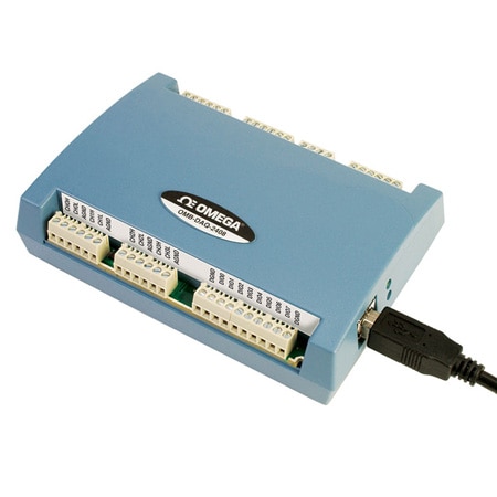
OMB-DAQ-2408-2AO
24-Bit Multifunction USB Data Acquisition Modules for Temperature and Voltage Measurement
Choisissez une variante
Output Signal
Remises de volume disponibles
Calendrier de remise sur volume
| Quantité | Prix unitaire |
|---|---|
| 1-4 | C$1 307.82 |
| 5-9 | C$1 242.43 |
| 10-24 | C$1 216.27 |
| 25-49 | C$1 163.96 |
| 50-99 | C$1 137.80 |
| 100+ | C$1 111.65 |
Ajouté à votre panier
Configuration terminée.
Veuillez ajouter au panier pour la conserver ou quitter la configuration
Veuillez ajouter au panier pour la conserver ou quitter la configuration
Échec de l'enregistrement des configurations, cliquez sur le bouton Configurer Recommencer
Spécifications du produit
<< Voir toutes les modèles de produits| Brand |
|
| A/D Conversion | ADS1256, 24-bit Sigma Delta |
| Analog I/O Note | Analog Input Note: ANALOG INPUT;A/D Converter Type: ADS1256, 24-bit Sigma Delta;A/D Data Rates: 3750 S/s, 2000 S/s, 1000 S/s, 500 S/s, 100 S/s, 60 S/s, 50 S/s, 25 S/s, 10 S/s, 5 S/s, 2.5 S/s;Throughput (Software-Selectable for Single Channel and Multiple Channels); Single Channel: 2.5 to 1102.94 S/s; Multiple Channels: 0.16 to 1102.94 Hz;Number of Channels: Up to 16 channels individually software-selectable as single ended (SE) or differential (DIFF); thermocouples require differential mode; for each channel configured as differential, you lose one single-ended channel;Input Isolation: 500 Vdc min between field wiring and USB interface;Channel Configurations: Temperature sensor input,;software-selectable to match sensor type; voltage input;Input Voltage Range; Thermocouple Mode: ±0.078125V; Voltage Mode (Software-Selectable); ±10V, ±5V, ±2.5V, ±1.25V, ±0.625V,; ±0.3125V, ±0.15625V, ±0.078125V;Absolute Maximum Input Voltage; CxH-CxL Relative to GND: ±22V max (power on), ±10V max (power off);Input Impedance: 10 MΩ (power on), 390Ω (power off);Input Leakage Current: ±20 nA;Input Voltage: >±22V (power on/off): ±1µ A max;Input Capacitance: 590 pf;Maximum Working Voltage (Signal + Common Mode); Voltage Mode: ±10.25V max;Common Mode Rejection Ratio; Thermocouple Mode (fIN = 60 Hz): 110 dB; Voltage Mode (fIN = 60 Hz, All Input Ranges): 90 dB;ADC Resolution: 24-bits;Crosstalk: Adjacent channels, 100 dB;Input Coupling: DC;Channel Gain Queue: Up to 64 elements, software-selectable channel and range;Warm-Up Time: 45 minutes min;Open Thermocouple Detect: Software-selectable for each channel;CJC Sensor Accuracy; 15 to 35°C: ±0.5°C typ; 0 to 55°C: ±1.0°C max |
| Bandwidth | 1 MHz |
| Breakdown Voltage | Drain to Source: 50 V |
| CMRR | Thermocouple Mode (fIN = 60 Hz): 110 dB, Voltage Mode (fIN = 60 Hz, All Input Ranges): 90 dB |
| Configuration Parameters | Alarm Functionality, Pull-Up/Down Configuration, Thermocouple Type Selection, User-Configurable Input/Output |
| Data Interface | Ethernet, USB 1.1, USB 2.0 |
| Data Interface Note | Configuration Method: TracerDAQ Software;Output Configuration: Digital: Each DIO bit can be independently read from (DIN) or written to (DOUT). DIN bits can be read at any time whether the DOUT is active or tri-stated.;Supported Operating System: Microsoft Windows® VISTA/7/8/10 (32-bit and 64-bit) |
| Digital I/O Note | DIGITAL INPUT Number of I/O: 8 channels Configuration: Each DIO bit can be independently read from (DIN) or written to (DOUT). DIN bits can be read at any time whether the DOUT is active or tri-stated. Input Voltage Range: 0 to 15V Input Type: CMOS (Schmitt trigger) Input Characteristics: 47 kΩ pull-up/pull-down resistor, 28 Ω series resistor Maximum Input Voltage Range: 0 to 20V max (power on/off, relative to DGND) Pull-Up/Pull-Down Configuration: All pins pulled up to 5V through individual 47 kΩ resistors (the J6 shorting block default position is pins 1 and 2) Pull-down capability is available by placing the J6 shorting block across pins 2 and 3 Transfer Rate (Software Paced): 500 port reads or single bit reads per second typ Input High Voltage: 1.3 to 2.2V Input Low Voltage: 1.5 to 0.6V Schmitt Trigger Hysteresis: 0.4V to 1.2 Output Characteristics: 47 kΩ pull-up, open drain (DMOS transistor) internally connected to DGND Pull-Up Configuration: All pins pulled up to 5V through individual 47 k? resistors (the J6 shorting block default position is pins 1 and 2). Transfer Rate (Software Paced) Digital Output: 500 port writes or single bit writes per second typ Output Voltage Range: 0 to 5V (no external pull up resistor, internal 47 Ωk pull-up resistors connected to 5V by default); 0 to 15V max Drain to Source Breakdown Voltage: 50V min, Off State Leakage Current: 1.0 µA Sink Current Capability: 150 mA max (continuous) per output pin 150 mA max (continuous) for all eight channels DMOS Transistor On-Resistance (Drain to Source): 4 Ω "Output Characteristics: 47 kΩ pull-up, open drain (DMOS transistor) internally connected to DGND Pull-Up Configuration: All pins pulled up to 5V through individual 47 k? resistors (the J6 shorting block default position is pins 1 and 2). Transfer Rate (Software Paced) Digital Output: 500 port writes or single bit writes per second typ Output Voltage Range: 0 to 5V (no external pull up resistor, internal 47 Ωk pull-up resistors connected to 5V by default); 0 to 15V max Drain to Source Breakdown Voltage: 50V min, Off State Leakage Current: 1.0 µA Sink Current Capability: 150 mA max (continuous) per output pin 150 mA max (continuous) for all eight channels DMOS Transistor On-Resistance (Drain to Source): 4 Ω "Output Characteristics: 47 kΩ pull-up, open drain (DMOS transistor) internally connected to DGND Pull-Up Configuration: All pins pulled up to 5V through individual 47 k? resistors (the J6 shorting block default position is pins 1 and 2). Transfer Rate (Software Paced) Digital Output: 500 port writes or single bit writes per second typ Output Voltage Range: 0 to 5V (no external pull up resistor, internal 47 Ωk pull-up resistors connected to 5V by default); 0 to 15V max Drain to Source Breakdown Voltage: 50V min, Off State Leakage Current: 1.0 µA Sink Current Capability: 150 mA max (continuous) per output pin 150 mA max (continuous) for all eight channels DMOS Transistor On-Resistance (Drain to Source): 4 Ω ;Cross talk: 100 dB;Transfer Rate: Digital: 500 port reads or single bit reads per second typ, Counter: System dependent, 500 reads or writes per second;Schmitt Trigger Hysteresis: 0.4V to 1.2V;Sink Current: 150 mA |
| Digital Input | Digital: Low = 0 Vdc |
| Digital Output | 5 V ,AOUTx pins, ±5.0 mA maximum |
| Electrical Connection | Screw Terminal |
| Electrical Output | 0 to 5 Vdc |
| Frequency Input Range | 1 MHz |
| Height | 36 mm |
| Impedance Input | 10 MΩ (power on), 390 Ω (power off) |
| Input Capacitance | Analog: 590 pf, Counter: 25 pf |
| Input Configuration | Connected Software |
| Input Type | Thermocouple, Voltage |
| Input Voltage Note | Absolute Maximum Input Voltage: Analog: CxH-CxL Relative to GND - ±22V max (Power On), ±10V maximum (Power Off), Digital: 0 to 20V maximum (Power On/Off, relative to DGND), Counter: CTR0, CTR1 relative to GND and DGND, ±20V maximum (Power On/Off) |
| Isolation | 500 Vdc Minimum between field Wiring and USB Interface |
| LED Indicators | Supply Status LED |
| Leakage Current | ±20 nA |
| Length | 127 mm |
| Memory | EEPROM: 4096 bytes |
| Microcontroller | One high-performance 8-bit RISC microcontroller with USB interface (non-isolated); one high‑performance 16-bit RISC microcontroller for measurements (isolated) |
| Number of Channels, Input | Analog: 16 SE/8 DIFF, Digital: 8, Counter: 2 |
| Number of Channels, Output | Digital: 8, Analog: 2 |
| Operating Temperature, Max | 50 °C |
| Operating Temperature, Min | 0 °C |
| Output Resolution | Analog: 16-bits |
| Output Settling Time | 10V step, 75 μs |
| Output Signal | Digital, Voltage |
| Pull-down Resistor | 47 kΩ |
| Pull-up Resistor | 47 kΩ |
| Relative Humidity | 0 to 90% RH non-condensing |
| Sampling Rate | 1 kHz (1,000 updates/second) |
| Sampling Rate Note | The maximum throughput of an OMB-DAQ-2408 module is 1.1 kS/s aggregate. The OMB-DAQ-2408 provides the ability to set conversion rates on a per-channel basis. This feature gives the user flexibility and control over noise averaging for each channel. Analog Input Throughput (Software-Selectable for Single Channel and Multiple Channels): Single Channel:2.5 to 1102.94 S/s, Multiple Channels: 0.16 to 1102.94 Hz Analog Output Throughput: Single-Channel: 1000 S/s maximum, system-dependent, Multi-Channel: 1000 S/s /#ch maximum, system-dependent |
| Slew Rate | 1.0 V/μs |
| Storage Temperature, Max | 85 °C |
| Storage Temperature, Min | -40 °C |
| Supply Current | 275 mA |
| Supply Power Note | Quiescent current, 275 mA (includes up to 10 mA for the status LED; does not include any potential loading of the digital I/O bits, 5V user terminal or the AOUTx outputs). 5V User Output Voltage Range: Available at terminal block pin 40, 4.75 to 5.25V 5V User Output Current: Available at terminal block pin 40, 10 mA maximum, Isolation: Measurement system to PC, 500 Vdc minimum |
| Supply Voltage | 5 Vdc |
| USB Cable Length | 3 m |
| Voltage Output | ±10 V (Calibrated), ±10.05V (Uncalibrated, software-selectable) |
| Warm Up Time | 45 min |
| Weight | 160 g |
| Width | 89 mm |
| Wire Gauge | 30 to 16 AWG |
| Voir toutes Spécs | |
PDF et manuels
Logiciels et pilotes
Afficher les notes et les avis
Rated 5 out of
5
by
petercat from
Meets our needs
We needed a DAQ with at least 4 channels, 24 bit resolution and better than 10 samples per second. This unit exceeds our need and works better than our previous DAQ from another vendor. The Pro version of the software is also better, and was worth the $200.
Date published: 2021-07-10
Rated 3 out of
5
by
Just A Guy from
Like anything, knowing how to use it matters
Really a 3.5 star product, and I'm a firm critic of things.
For the average user of DAQ based control & metrology, this device is not user friendly. However, for operating as an I/O control point in an integrated system, it's good. Digital I/O serve as TTL 5V triggers, reasonably stable analog signals act as voltage references for measurement systems, and the temperature inputs are many in #. They can have some instability in thermal measurement (bummer!) and measurement frequency definitely matters when data logging (you need to run the InstaCal configuration utility to set this up). Your application dictates your needs, so go learn on how to setup things to measure well.
One of the downsides is, when connecting to any new PC it often requires you to go setup in InstaCal to establish a baseline configuration before you can use it. Also, the temperature readings are only useful to 0.1°C and nothing deeper.
Maybe not the most optimal I/O device out there for the $$, but certainly if you just need an API-ready instrument, this is a good place to start.
Date published: 2020-11-30
Rated 1 out of
5
by
Anonymous from
Too low sampling rate
The device is not able to reach above 350 Hz of sampling which is low for most scientific experiments.
Date published: 2020-09-23
Rated 2 out of
5
by
hendrigl from
Very difficult to use
I am trying to replace a Labjack T7 with the DAQ-2408 and find it nearly impossible to understand and use the Universal Library .dll with a Power Basic program. I have not been able to read a voltage or a thermocouple. The 4 different analog input library calls each give a different return value and there seems to be no way of telling which is correct. The reference files do not clearly give the data needed to initialize and startup the 2408. I have used the C, C#, and Visual Basic examples in trying to understand the units to put in a library call. For instance, cbVIn32(BoardNum,chan,Gain,Datavald,Options) has a term Gain. What the value should be I have not been able to locate in the documentation.
I have a lot of other comments, too many for this listing.
Gerald Hendrickson
Date published: 2018-04-17