Bienvenue sur notre nouveau site Web, vous avez rencontré un problème ou un bug? Veuillez le signaler ici
DRST-FR-Freq-Sig-Cond
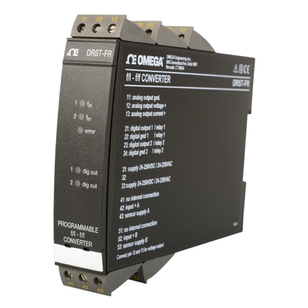
DIN Rail Frequency Input Signal Conditioner | Configurable
Modèles en stock
- Configurable with a standard PC and TXUN-KIT communications unit
- Pulse Calculator
- Frequency Generator
- Galvanic Isolation
DRST-FR-Freq-Sig-Cond
Depuis
C$
715.96
Modèles en stock
L'aperçu du produit
- Approvals Note EMC:2014/30/EU, LVD:2014/35/EU, EAC:TR-CU 020/2011
- Calibration Temperature, Max 28 °C
- Calibration Temperature, Min 20 °C
- Electrical Output 0 to 20 mA
- EMC Standard NAMUR NE 21
- Enclosure Ratings IP20
- Frequency Measurement Range 0 to 20 kHz
- Fuse Rating 400 mA SB / 250 Vac
- Height 109 mm
- Isolation 3750 Vac
- Length 130 mm
- Linearity Error < 0.1% of span
- Load Resistance Voltage Output : ≥ 500 kΩ, Current Output : ≤ 600 Ω
- Mounting DIN Rail 46277
- Noise Calibration >60 dB
- Operating Temperature, Max 60 °C
- Operating Temperature, Min -20 °C
- Optional Power Note 0 to 999 s
- Output Value Process
- Power Consumption 3.5 W, Internal - 3 W
- Relative Humidity <95% RH
- Screw Terminal Torque 0.5 Nm
- Signal Dynamics Output 16 bit
- Stability Load Stability: ≤0.01% of span/100 Ω
- Supply Power Type AC/DC
- Update Rate 20 ms
- Warm Up Time 1 min
- Weight 240 g
- Width 23.5 mm
Advanced Features
• The DRST-FR signal converter can be configured with OMSET software in a standard PC and the TXUN-KIT communications unit.
Application
• The f/I function performs frequency to current and voltage conversion.
• The f/f function can be used for pulse division or multiplication and as a buffer collecting fast pulse trains.
• A scale factor may be entered in all functions. Using both digital inputs, pulse addition or subtraction are possible.
• The frequency generator function is used as e.g. a time base or clock generator.
• Input and supply polarity reversal protection. Current and voltage output signals galvanically separated from the supply and the inputs.
• Programmable digital outputs including NPN, PNP or relay options.
Technical Characteristics
• 5 front LEDs, indicating f1 and f2 active inputs (not NPN), Dig.out.1 and 2 active outputs, and a programmable error signal.
• Analog current output can be configured to any current within 0 to 20 mA range.
• Voltage output range is selectable between 0 to 10 Vdc and 0 to 1 Vdc by use of internal jumpers.
• Input range: Frequency: 0 to 20,000 Hz Sensor types: NAMUR, tacho, NPN, PNP, TTL, S0
• Output range: Current and voltage output: 0 to 20 mA / 0...10 V Relay outputs: 0 to 20 Hz NPN and PNP output as f/f: 0 to 1000 Hz NPN and PNP output as generator: 0 to 20,000 Hz
Specifications
Environmental Conditions
Operating Temperature: -20 to 60°C
Calibration Temperature: 20 to 28°C
Relative Humidity: < 95% RH (non-cond.)
Protection Degree: IP20
Mechanical Specifications
Dimensions (HxWxD): 109 x 23.5 x 130 mm
Weight Approx: 240 g
DIN Rail Type: DIN 46277
Wire Size: 1 x 2.5 mm2 stranded wire
Screw Terminal Torque: 0.5 Nm
Common Specifications
Supply
Supply Voltage, Universal:21.6 to 253 Vac, 50 to 60 Hz or 19.2 to 300 Vdc
Fuse: 400 mA SB / 250 Vac
Max. Required Power: 3.5 W
Internal Power Dissipation:3 W
Isolation Voltage
Isolation Voltage, Test/Working: 3.75 kVac / 250 Vac
Power-Up Delay: 0 to 999 s
Warm-Up Time:1 min.
Programming: Loop Link
Signal/Noise Ratio: Min. 60 dB
Response Time, Analog:< 60 ms + period
Response Time, Digital Output: < 50 ms + period
Signal Dynamics, Output:16 bit
Effect of Supply Voltage Change: < 0.005% of span/Vdc
Auxiliary Voltage: NAMUR Supply: 8.3 Vdc ± 0.5 Vdc / 8 mA
S0 Supply: 17 Vdc/20 mA
NPN/PNP Supply: 17 Vdc/20 mA
Special Supply (Programmable): 5 to 17 Vdc/20 mA
Temperature Coefficient:< ± 0.01% of span/°C
Linearity Error: < 0.1% of span
EMC Immunity Influence: < ± 0.5%
Input Specifications
Common Input Specifications
Max. Offset: 90% of selected max. frequency
Measurement Range: 0 to 20 kHz
Min. Measurement Range: 0.001 Hz
Max. Frequency, with Input Filter ON: 50 Hz
Min. Period Time with Input Filter ON: 20 ms
Input Types: NAMUR acc. to DIN 19234
Input Types:Tacho
Input Types:NPN/PNP
Input Types:2-phase encoder
Input Types:TTL
Input Types:S0 acc. to DIN 43864
Output Specifications
Common Output Specifications
Updating Time: 20 ms
Current Output
Signal Range: 0 to 20 mA
Min. Signal Range: 5 mA
Load (@ Current Output): ≠¤ 600 Ω
Load Stability: ≠¤ 0.01% of span/100 Ω
Current Limit: < 23 mA
Voltage Output
Signal Range: 0 to 10 Vdc
Min. Signal Range: 250 mV
Load (@ Voltage Output): ≠¥ 500 kΩ
Relay Output
Max. Switching Frequency: 20 Hz
Max. Voltage: 250 VRMS
Max. Current: 2 AAC
Max. AC Power: 100 VA
Max. Load at 24 Vdc:1 A
Other Output Types: Active outputs (NPN/PNP)
Other Output Types: f/f Converter Output
Other Output Types: Frequency generator
Of Span: = of the presently selected range
Observed Authority Requirements
EMC: 2014/30/EU
LVD: 2014/35/EU
EAC: TR-CU 020/2011
PDF et manuels
Accessories
Afficher les notes et les avis
Rated 5 out of
5
by
BT Hello from
Valuable Programmable Signal Converter
This product fits our use since it is stable and easy to use.
Date published: 2023-02-28
Is the TXUN-KIT require for setup?
Thank you for your question. The max input voltage from a tach is 80 VAC pp
Date published: 2023-11-17
Hi, What is the maximum Input Voltage signal ( From Tacho) it can handle? Thanks.
Thank you for your question. Max. input voltage......................... 80 VAC pp
Date published: 2023-12-11
is it possible to take one input signal and condition it into two outputs simultaneously? for example a analog output scaled from 0-5VDC and a conditioned square wave of 10Vpp that matches the input frequency? thank you in advance
Hello Joel
I'm sorry it does not have that capability, though what you can do is connect the output of the device to a DRSL-SP2 signal splitter and it can split it to two output signals.
Date published: 2020-04-03
Does this model have any shock test certification. other certification /approvals availble
Hello, thank you for your question. There are no certifications related to shock as we don't perform that kind of testing for signal conditioners.
Date published: 2024-05-28