1-800-663-4209 | Vos commentaires sont importants, répondez à un sondage rapide commentaires sur le site web
DRST-DC-Univ-BP-Sig-Cond
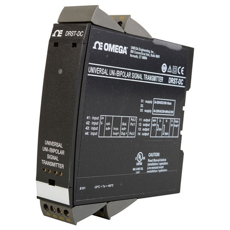
DIN Rail Universal Uni/Bipolar DC Signal Conditioner
Modèles en stock
- Measures Uni-/Bipolar DC Current and Voltage Signals
- Passive/Active Current Output and Buffered Voltage Output
- Extremely Good Signal Dynamics for Spans from 25 mV to 300 VDC
- Fast < 20 ms Response Time and Excellent 0.05% Accuracy
DRST-DC-Univ-BP-Sig-Cond
Depuis
C$
395.51
Modèles en stock
L'aperçu du produit
- Approvals UL, RoHS
- Approvals Note UL: UL 508/CC22.2 no. 14, LVD: 2014/35/EU, EMC: 2014/30/EU, RoHS: 2011/65/EU
- Bandwidth > 40 Hz
- Calibration Temperature, Max 28 °C
- Calibration Temperature, Min 20 °C
- Display Type Programmer
- Electrical Output 0 to 23 mA
- EMC Immunity Note NAMUR NE21, A Criterion, Burst: < ±1% of span Conducted Emission, class A: 150 kHz to 10 MHz
- EMC Standard NAMUR NE 21
- Enclosure Ratings IP20
- Height 109 mm
- Isolation 2.3 kVac
- Length 104 mm
- Load Resistance Current Output: 1000 Ω/± 20 V @ ±20 mA, Voltage Output: 2 kΩ, Buffered Voltage Output: > 500 kΩ min
- Mounting DIN Rail 35 mm Standard, EN 60715
- Noise Calibration >60 dB
- Operating Temperature, Max 60 °C
- Operating Temperature, Min -20 °C
- Output Value Process
- Power Consumption 2.5 W
- Power Dissipation 2.0 W
- Relative Humidity <95% RH
- Screw Terminal Torque 0.5 Nm
- Signal Dynamics Input 24 bit
- Signal Dynamics Output 18 bit
- Stability Load Stability: ≤0.01% of span/100 Ω
- Storage Temperature, Max 85 °C
- Storage Temperature, Min -20 °C
- Supply Power Type AC/DC
- Voltage Loss Input Voltage Drop: 0.6 V @ 20 mA nom.
- Weight 250 g
- Width 23.5 mm
- Wire Gauge 26 to 14 AWG
Application
• Fast < 20 ms response time for measuring signals produced by torque, position, current & acceleration sensors.
• User configurable bipolar or unipolar I/O means the DRST-DC is suitable for nearly any DC voltage or current conversion.
• Freely programmable between ± 300 VDC and ± 100 mA. The excitation source allows measurement of a 2-wire or 3-wire transmitter, or a potentiometer.
• Converts narrow bipolar inputs to wide bipolar or unipolar outputs, e.g., ± 1 volt input = ± 10 volt or 4 to 20 mA output.
• Configurable input limits control the output value for increased safety.
• ± 20 VDC buffered voltage output for controlling devices like the PVG 32 valve (6 to 18 VDC).
Technical Characteristics
• The latest analog and digital techniques are used to obtain maximum accuracy and immunity to interference.
• Possibility of output safety read back by selecting 4 to 20 mA output.
• The current output can drive up to 1000 Ω, with an adjustable response time of 0.0…60.0 seconds.
• Exceptional mA output load stability of < 0.001% of span/100 Ω.
• Meets the NAMUR NE21 recommendations, ensuring high accuracy in harsh EMC environments.
• Meets the NAMUR NE43 recommendations, allowing the control system to easily detect a sensor error.
• Each unit is tested to a high 2.3 kVAC, 3-port galvanic isolation level.
• Excellent signal to noise ratio of > 60 dB.
Mounting/Installation/Programming
• Very low power consumption means units can be mounted side by side without an air gap – even at 60°C (140ºF) ambient temperature.
• Configuration, monitoring, 2-point process calibration and more are accomplished using either the DRSL-Display detachable display or the DRST-CM detachable digital communication enabler.
• All programming can be password-protected.

Specifications
Environmental Conditions
Operating Temperature: -20 to 60°C
Storage Temperature: -20 to 85°C
Calibration Temperature: 20 to 28°C
Relative Humidity: < 95% RH (non-cond.)
Protection degree: IP20
Mechanical Specifications
Dimensions (H x W x D): 109 x 23.5 x 104 mm
Dimensions (H x W x D) with 4501/4511: 109 x 23.5 x 116/131 mm
Weight Approx: 250 g
Weight Incl. 4501/4511 (approx.): 285 g/350 g DIN Rail Type: DIN EN 60715/35 mm
Wire Size: 0.13 to 2.08 mm2 AWG 26 to 14 stranded wire
Screw Terminal Torque: 0.5 Nm
Common Specifications
Supply
Supply Voltage, Universal: 21.6 to 253 VAC, 50 to 60 Hz or 19.2 to 300 VDC
Max. Required Power: = 2.5 W
Internal Power Dissipation: = 2.0 W
Isolation Voltage
Test Voltage: 2.3 kVAC
Working Voltage: 250 VAC (reinforced)/500n VAC (basic)
Response Time:
Response Time: (0 to 90%, 100 to 10%) < 20 ms
Auxiliary Supplies
2-wire Loop Supply: > 16 V @ 20 mA
3-wire Loop Supply: > 18 to < 28 V @ 23 to 0 mA
Loop Supply Limitation: 27 to 35 mA avg., < 80 mA peak
Reference Voltage: 2.5 VDC ± 0.5%
Reference Voltage, Load: 0 to 15 mA
Current Limit, Reference Voltage: < 60 mA
Programming: Communication enabler 4511/Programming front 4501
Signal Dynamics, Input: 24 bit
Signal Dynamics, Output: 18 bit
Signal/Noise Ratio: > 60 dB
Bandwidth: > 40 Hz
Accuracy: Better than 0.05% of selected range
EMC Immunity Iinfluence: < ± 0.5% of span
Extended EMC Immunity: NAMUR
NE21, A Criterion, Burst: < ± 1% of span Conducted Emission, class A: 150 kHz to 10 MHz
Input Specifications
Current Input
Signal Range: ± 100 mA
Programmable Measurement Ranges: 0 to 1, 0 to 5, 1 to 5, 0 to 20, 4 to 20, ± 1, ± 5, ± 10, ± 20, ± 50, ± 100 mA
Custom Configurable Signal Range: ± 100 mA
Min. Measurement Range (span): 0.5 mA
Input Voltage Drop: 0.6 V @ 20 mA nom.
Voltage Input
Signal range: ± 300 VDC
Programmable Measurement Ranges: 0 to 0.1, 0 to 1, 0.2 to 1, 0 to 2.5, 0 to 5, 1 to 5, 0 to 10, 2 to 10, 0 to 100,
0 to 300, ± 0.1, ± 1, ± 2.5, ± 5, ± 10, ± 100, ± 300 V
Custom Configurable Signal Range:± 300 V
Min. Measurement Range (span): 25 mV
Input Resistance: Nom. 3 MΩ (> 2.5 VDC)
Input Resistance:Nom. > 10 MΩ (= 2.5 VDC)
Potentiometer Input
3-wire Potentiometer Input: 0 to 100%
Reference Voltage: 2.5 V
Calibration Resistance: 5 kΩ
Min. Potentiometer Resistance: 200 Ω
Output Specifications
Current Output
Signal Range: 0 to 23 mA (unipolar)
Signal Range: -23 to 23 mA (bipolar)
Custom Config. Output Range: ± 20 mA
Min. Signal Range: 4 mA
Load (@ Current Output): = 1000 Ω/± 20 V @ ± 20 mA
Current Limit: = 28 mA (unipolar)
Current Limit: ± 28 mA (bipolar)
Load Stability: = 0.001% of span / 100 Ω
Response Time, Programmable: 0.0 to 60.0 s
Passive 2-wire mA Output
Programmable Ranges: 0 to 20 and 4 to 20 mA
Ext. 2-Wire Loop Supply Range: 3.5 to 28.8 VDC
Voltage Output
Programmable Signal Ranges: 0/0.2 to 1; 0/1 to 5 ; 0/2 to 10 V
Programmable Signal Ranges: ± 1, ± 5 and ± 10 V
Programmable Signal Ranges:Direct or Inverted action
Load (@ Voltage Output): = 500 kΩ
Response Time, Programmable: 0.0 to 60.0 s
Shunted Voltage Output
Signal Range: ± 1.2 V/± 12 V
Programmable Standard Ranges: 0 to 1, 0 to 2.5, 0 to 5, 1 to 5, 0 to 10, 2 to 10 V ± 1, ± 2.5, ± 5, ± 10 V
Min. Span: 0.8 V
Custom Config. Output Range: ± 10 V
Load, Min: > 500 kΩ Buffered Voltage Output
Signal range: ± 23 V
Programmable Standard Ranges: 0 to 1, 0.2 to 1, 0 to 2.5, 0 to 5,1 to 5, 0 to 10, 2 to 10, 0 to 20, 4 to 20; ± 1, ± 2.5, ± 5, ± 10, ± 20 V
Min. Span: 0.8 V
Custom Config. Output Range: ± 20 V
Current Limit: < 50 mA
Load, Min: > 2 kΩ
Observed Authority Requirements
LVD: 2014/35/EU
EMC: 2014/30/EU
RoHS: 2011/65/EU
Approvals
UL: UL 508/CC22.2 no. 14
• Fast < 20 ms response time for measuring signals produced by torque, position, current & acceleration sensors.
• User configurable bipolar or unipolar I/O means the DRST-DC is suitable for nearly any DC voltage or current conversion.
• Freely programmable between ± 300 VDC and ± 100 mA. The excitation source allows measurement of a 2-wire or 3-wire transmitter, or a potentiometer.
• Converts narrow bipolar inputs to wide bipolar or unipolar outputs, e.g., ± 1 volt input = ± 10 volt or 4 to 20 mA output.
• Configurable input limits control the output value for increased safety.
• ± 20 VDC buffered voltage output for controlling devices like the PVG 32 valve (6 to 18 VDC).
Technical Characteristics
• The latest analog and digital techniques are used to obtain maximum accuracy and immunity to interference.
• Possibility of output safety read back by selecting 4 to 20 mA output.
• The current output can drive up to 1000 Ω, with an adjustable response time of 0.0…60.0 seconds.
• Exceptional mA output load stability of < 0.001% of span/100 Ω.
• Meets the NAMUR NE21 recommendations, ensuring high accuracy in harsh EMC environments.
• Meets the NAMUR NE43 recommendations, allowing the control system to easily detect a sensor error.
• Each unit is tested to a high 2.3 kVAC, 3-port galvanic isolation level.
• Excellent signal to noise ratio of > 60 dB.
Mounting/Installation/Programming
• Very low power consumption means units can be mounted side by side without an air gap – even at 60°C (140ºF) ambient temperature.
• Configuration, monitoring, 2-point process calibration and more are accomplished using either the DRSL-Display detachable display or the DRST-CM detachable digital communication enabler.
• All programming can be password-protected.
Specifications
Environmental Conditions
Operating Temperature: -20 to 60°C
Storage Temperature: -20 to 85°C
Calibration Temperature: 20 to 28°C
Relative Humidity: < 95% RH (non-cond.)
Protection degree: IP20
Mechanical Specifications
Dimensions (H x W x D): 109 x 23.5 x 104 mm
Dimensions (H x W x D) with 4501/4511: 109 x 23.5 x 116/131 mm
Weight Approx: 250 g
Weight Incl. 4501/4511 (approx.): 285 g/350 g DIN Rail Type: DIN EN 60715/35 mm
Wire Size: 0.13 to 2.08 mm2 AWG 26 to 14 stranded wire
Screw Terminal Torque: 0.5 Nm
Common Specifications
Supply
Supply Voltage, Universal: 21.6 to 253 VAC, 50 to 60 Hz or 19.2 to 300 VDC
Max. Required Power: = 2.5 W
Internal Power Dissipation: = 2.0 W
Isolation Voltage
Test Voltage: 2.3 kVAC
Working Voltage: 250 VAC (reinforced)/500n VAC (basic)
Response Time:
Response Time: (0 to 90%, 100 to 10%) < 20 ms
Auxiliary Supplies
2-wire Loop Supply: > 16 V @ 20 mA
3-wire Loop Supply: > 18 to < 28 V @ 23 to 0 mA
Loop Supply Limitation: 27 to 35 mA avg., < 80 mA peak
Reference Voltage: 2.5 VDC ± 0.5%
Reference Voltage, Load: 0 to 15 mA
Current Limit, Reference Voltage: < 60 mA
Programming: Communication enabler 4511/Programming front 4501
Signal Dynamics, Input: 24 bit
Signal Dynamics, Output: 18 bit
Signal/Noise Ratio: > 60 dB
Bandwidth: > 40 Hz
Accuracy: Better than 0.05% of selected range
EMC Immunity Iinfluence: < ± 0.5% of span
Extended EMC Immunity: NAMUR
NE21, A Criterion, Burst: < ± 1% of span Conducted Emission, class A: 150 kHz to 10 MHz
Input Specifications
Current Input
Signal Range: ± 100 mA
Programmable Measurement Ranges: 0 to 1, 0 to 5, 1 to 5, 0 to 20, 4 to 20, ± 1, ± 5, ± 10, ± 20, ± 50, ± 100 mA
Custom Configurable Signal Range: ± 100 mA
Min. Measurement Range (span): 0.5 mA
Input Voltage Drop: 0.6 V @ 20 mA nom.
Voltage Input
Signal range: ± 300 VDC
Programmable Measurement Ranges: 0 to 0.1, 0 to 1, 0.2 to 1, 0 to 2.5, 0 to 5, 1 to 5, 0 to 10, 2 to 10, 0 to 100,
0 to 300, ± 0.1, ± 1, ± 2.5, ± 5, ± 10, ± 100, ± 300 V
Custom Configurable Signal Range:± 300 V
Min. Measurement Range (span): 25 mV
Input Resistance: Nom. 3 MΩ (> 2.5 VDC)
Input Resistance:Nom. > 10 MΩ (= 2.5 VDC)
Potentiometer Input
3-wire Potentiometer Input: 0 to 100%
Reference Voltage: 2.5 V
Calibration Resistance: 5 kΩ
Min. Potentiometer Resistance: 200 Ω
Output Specifications
Current Output
Signal Range: 0 to 23 mA (unipolar)
Signal Range: -23 to 23 mA (bipolar)
Custom Config. Output Range: ± 20 mA
Min. Signal Range: 4 mA
Load (@ Current Output): = 1000 Ω/± 20 V @ ± 20 mA
Current Limit: = 28 mA (unipolar)
Current Limit: ± 28 mA (bipolar)
Load Stability: = 0.001% of span / 100 Ω
Response Time, Programmable: 0.0 to 60.0 s
Passive 2-wire mA Output
Programmable Ranges: 0 to 20 and 4 to 20 mA
Ext. 2-Wire Loop Supply Range: 3.5 to 28.8 VDC
Voltage Output
Programmable Signal Ranges: 0/0.2 to 1; 0/1 to 5 ; 0/2 to 10 V
Programmable Signal Ranges: ± 1, ± 5 and ± 10 V
Programmable Signal Ranges:Direct or Inverted action
Load (@ Voltage Output): = 500 kΩ
Response Time, Programmable: 0.0 to 60.0 s
Shunted Voltage Output
Signal Range: ± 1.2 V/± 12 V
Programmable Standard Ranges: 0 to 1, 0 to 2.5, 0 to 5, 1 to 5, 0 to 10, 2 to 10 V ± 1, ± 2.5, ± 5, ± 10 V
Min. Span: 0.8 V
Custom Config. Output Range: ± 10 V
Load, Min: > 500 kΩ Buffered Voltage Output
Signal range: ± 23 V
Programmable Standard Ranges: 0 to 1, 0.2 to 1, 0 to 2.5, 0 to 5,1 to 5, 0 to 10, 2 to 10, 0 to 20, 4 to 20; ± 1, ± 2.5, ± 5, ± 10, ± 20 V
Min. Span: 0.8 V
Custom Config. Output Range: ± 20 V
Current Limit: < 50 mA
Load, Min: > 2 kΩ
Observed Authority Requirements
LVD: 2014/35/EU
EMC: 2014/30/EU
RoHS: 2011/65/EU
Approvals
UL: UL 508/CC22.2 no. 14
PDF et manuels